DC-DC converters and pixels.. getting your feet wet?

plasmadrive

Full time elf
Joined
Jan 12, 2012
Messages
248
Location
Elk Grove, CA
David_AVD said:
Another thing to be careful with is that when the input voltage to the DC-DC converter decreases (say due to voltage drop in the cabling), the input current increases.

If the input cabling is too thin, this can cause a snowball effect; more voltage drop -> more current draw -> even more voltage drop - even more current draw, etc.

The end result can be a input cabling overheating, a fuse blowing or the upstream power supply shutting down.
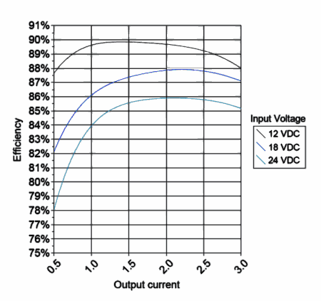
The set up would have to be pretty marginal for this to happen.. but theoretically, I guess it could..
 

plasmadrive

Full time elf
Joined
Jan 12, 2012
Messages
248
Location
Elk Grove, CA
plasmadrive said:
David_AVD said:
Here's a chart for a random 5V 3A DC-DC converter:
dcz5-eff.png

As you can see, the efficiency drops off markedly at low output currents. This means there's proportionally more wasted energy (heat dissipated), but luckily at those lower currents the absolute waste is fairly low.

Also (for this example converter), the efficiency is lower when the input voltage is higher. This may not be the case for all converters though. You'd really need to check the efficiency for the particular input voltage, output voltage and output current on the chosen converter.

What all of this means is that you may need to factor in these losses when calculating the power supply requirements. So if your RGB strip draws 36W on full white, the power supply could need to supply up to 45W of power to the DC-DC converter to make it happen.

Anyway, this is just some additional information to the original post to make sure people don't get caught short with power in their displays.

Not all are created equal. That indeed may be a typical chart.. and perhaps in my write up I should have put something about testing what you are using prior to final numbers.. or maybe even bumped up the head room factor..

In the next week or so as time permits I will grab one of the converters I used and retest it. This time I will use a true RMS meter on both the in and out.. Lets see where it takes us. Maybe I just got a sweet one for my original testing or maybe my power supply meter was inaccurate with the non linear load. I will report back with I have time.

OK.. I finally got a chance to do this.. with a 5v 5amp converter (the one I tested) running at about 3.3 amps I was getting right around 93-94%. I don't know it this one is just a good one or that is typical. Now they are saying fully loaded up to 95% in the specs. So.. who knows.. anyway.. with a 24v input my system for the Plasma Icicles worked perfectly.. I also have now ordered more converters for my mini pixel trees.. They should be fun and I can run them all off one weatherproof supply with converters. I don't have to box any of it.. I Like that part.
 

AussieDoug

Full time elf
Joined
Dec 1, 2012
Messages
376
AAH said:
Just be a bit careful Doug. Assuming the buck converters are 90% efficient you'll only get 540W out of converters assuming the power supply is running at 100% and you have no cable losses. The 90% is possibly being generous but I'm assuming nice efficient ones as they are large. There will be cable losses of course but it will depend on whether the cable run is 1m or 10m obviously.

AussieDoug said:
So I have decided to dive into the DC - DC convertors to run my hedge matrix. What I have is a 24v 26amp 600w PSU to 3 x 12v 25amp 300w buck convertors. These will be running a 720 pixels.
There is 3 convertors at 300w each so the 480watts total for the 720 LEDs shouldn't be an issue. They will only be running 240 LEDs each, that's about 160 watts which is only just over 50% capacity. I will make sure that there is a solid 24v at each convertor, but they are a variable input voltage of 15v - 40v so I could bump it up a bit if needed.
 

David_AVD

Grandpa Elf
Community project designer
Generous elf
Joined
Jun 12, 2010
Messages
4,681
Location
Victoria Point (Brisbane)
plasmadrive said:
OK.. I finally got a chance to do this.. with a 5v 5amp converter (the one I tested) running at about 3.3 amps I was getting right around 93-94%. I don't know it this one is just a good one or that is typical.

So that would have been approx 0.74A (740mA) on the 24V side?

Do you have a link to that converter? It sounds like a good one to use.
 

plasmadrive

Full time elf
Joined
Jan 12, 2012
Messages
248
Location
Elk Grove, CA
David_AVD said:
plasmadrive said:
OK.. I finally got a chance to do this.. with a 5v 5amp converter (the one I tested) running at about 3.3 amps I was getting right around 93-94%. I don't know it this one is just a good one or that is typical.

So that would have been approx 0.74A (740mA) on the 24V side?

Do you have a link to that converter? It sounds like a good one to use.

Here are the ones I used for the Plasma Icicles and the one I tested. It tested higher efficiency than claimed. http://www.prodctodc.com/dc-step-down-voltage-regulator-dc-1224v-to-5v5a25w-buck-converter-module-waterproof-car-power-supply-p-123.html#.VAvEn2NhKbh

They also have a newer version that claims up to 96% but in the spec line says 90%.. Not sure which is correct.
http://www.prodctodc.com/dc-buck-converter-12v24v-to-5v-25w-car-power-supply-step-down-buck-converter-waterproof-p-133.html#.VAvFRmNhKbg
 

David_AVD

Grandpa Elf
Community project designer
Generous elf
Joined
Jun 12, 2010
Messages
4,681
Location
Victoria Point (Brisbane)
That's odd because I tested what looks to be the same type as the first link and got 85% efficiency at 3.75 Amps load.
 

plasmadrive

Full time elf
Joined
Jan 12, 2012
Messages
248
Location
Elk Grove, CA
David_AVD said:
That's odd because I tested what looks to be the same type as the first link and got 85% efficiency at 3.75 Amps load.

I only tested one of the 20 something I have.. the numbers are what they are.. When I get some time I will pull a couple out of the bin and see what they do. I only did the one that have had hanging around the bench for the last year. The others are up high in bins.. coming down soon though.. I will let you know what I find out. Maybe I got a hot one or maybe you got a so so one.. Let's see what a few others work out to be.
 

plasmadrive

Full time elf
Joined
Jan 12, 2012
Messages
248
Location
Elk Grove, CA
David_AVD said:
That's odd because I tested what looks to be the same type as the first link and got 85% efficiency at 3.75 Amps load.
OK.. this was bothering me so I went back and hooked up this one converter and tested it again.

Using a Fluke 73 for current on the 24v side and an Extech EX830 for current on the 5v side and a Klein MM200 for the voltage on the 5v side and the power supply volt meter for the 24v side.... here is what I found.

24.0vdc primary to the converter at the power supply. Leads are short and #14 wire so I didn't measure at the converter (which is where I know I should measure but I only have so many meters on hand now that I am retired).

.739 amps on the 24vdc side.

5.02vdc at the converter output.

3.3amps load current via the Extech on the load side

Here is the kicker... with the clamp on RMS amp probe I read 3.3 amp DC... however, if I move the clamp around a bit I can get a reading of 3.2 amps.. If I reverse it on the wire I can get down to 3.1amps if I find the right spot in the clamp on field.

Conclusion: My measuring system is flawed due to possible meter inaccuracies. My measurements could very well be OK.. but I since I can vary the current reading with meter position on the clamp vs the wire, I can not be 100% certain. A delta of only .2amps reading on the secondary will change the calculated efficiency from 93-87%.
 

David_AVD

Grandpa Elf
Community project designer
Generous elf
Joined
Jun 12, 2010
Messages
4,681
Location
Victoria Point (Brisbane)
You need a static resistive load and a proper inline (with the wiring) current meter with "low burden voltage" to measure it correctly. Failing to do is can result in optimistic readings due to errors introduced by the measurement method.

I measured the currents inline with a DMM on the 10A scale to assure a low burden voltage. Also, the voltages must be measured close to the DC-DC converter, not at the load and PSU else you'll be including the wiring resistance (losses) in the measurements.
 

plasmadrive

Full time elf
Joined
Jan 12, 2012
Messages
248
Location
Elk Grove, CA
David_AVD said:
You need a static resistive load and a proper inline (with the wiring) current meter with "low burden voltage" to measure it correctly. Failing to do is can result in optimistic readings due to errors introduced by the measurement method.

I measured the currents inline with a DMM on the 10A scale to assure a low burden voltage. Also, the voltages must be measured close to the DC-DC converter, not at the load and PSU else you'll be including the wiring resistance (losses) in the measurements.

Actually I disagree with the need for a resistive load.. static yes.. resistive.. if you are writing specs perhaps.. but I am more interested in what they will do with the load I, and most here, will use them on. Much more relevant information to me.

The primary side was with an inline on a 10 amp scale.. The wire resistance in the primary was very minimal and not that relevant. 3/4 of an amp on #14 wire less than a foot long each way is not much to worry about, (.005 ohms in total) Remember, this is a hobby board.. :eek:

The secondary voltage is at the load for a reason.. the wiring from the converter, which is part of the equation, can't be disconnected so it has to be considered as part of the converter. There is no other way. it was connected to the load directly.

My real issue is with the clamp on amp meter on the secondary. There is where I was able to cause a variance of .2amps.. and I still don't know which is accurate. If I latch on to another meter I may revisit this, but not going to hold my breath.. I found where and why we differ (at least I think so), so I am satisfied.

Thanks for keeping me checkin!
 

David_AVD

Grandpa Elf
Community project designer
Generous elf
Joined
Jun 12, 2010
Messages
4,681
Location
Victoria Point (Brisbane)
The reason I mentioned a static load was to ensure that the primary and secondary voltage and current measurements were all taken under the same conditions.

A resistive load is even better as there will be less error in the measurements due to the meter's interpretation of the non-steady load.

Either way the clamp meter is probably not the best tool for the job, but at least gets you ballpark measurements. :)
 

AAH

I love blinky lights :)
Community project designer
Joined
Dec 27, 2010
Messages
4,190
Location
Eaglehawk
I have found that DC clamps are fairly variable especially at low currents. They often need the DC offset zeroed before use as well.
 

plasmadrive

Full time elf
Joined
Jan 12, 2012
Messages
248
Location
Elk Grove, CA
David_AVD said:
The reason I mentioned a static load was to ensure that the primary and secondary voltage and current measurements were all taken under the same conditions.

A resistive load is even better as there will be less error in the measurements due to the meter's interpretation of the non-steady load.

Either way the clamp meter is probably not the best tool for the job, but at least gets you ballpark measurements. :)

I know why the resistive load.. but just not real relevant for my purposes.. I don't light up resistors.. Well, not intentionally anyway! :D ha ha.. :eek:

Yeah, I kinda already knew where we differed but I needed to make sure.. I got rid of almost all my meters when I threw in the towel.. so that is what I had to work with.. The resolution is also only x.x amps... not lab gear for sure.. but it does get you in the ball park!
 

multicast

Senior elf
Joined
Jul 13, 2013
Messages
715
I'm quite a happy camper today. After redesigning my Switch mode power supplies i've achieved a 94.1% efficencency and that its working pretty well. Yes, it would be possible to extract a few more percentage, but it becomes a cost benefit and size equation!
 

plasmadrive

Full time elf
Joined
Jan 12, 2012
Messages
248
Location
Elk Grove, CA
Qiang Fu Kiwi said:
I'm quite a happy camper today. After redesigning my Switch mode power supplies i've achieved a 94.1% efficencency and that its working pretty well. Yes, it would be possible to extract a few more percentage, but it becomes a cost benefit and size equation!

Nice!
 
Top