That is all I want to know (Other improvement suggestions welcome of course).
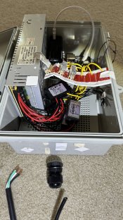
I’ve had my power supply and controller (pi4) in a non-waterproof box for my initial testing and buying-more-stuff phase, but hoping to maybe have a small show this year, which means everything needs to be outside and waterproof. I bought an electrical box that I thought everything would fit in, but it looks a little cramped once everything is actually inside.
Please ignore the mess of electrical tape. If this setup works, I’ll be 3D printing some ‘shelves’ and brackets to hold everything together (The tape is just for visualization purposes).

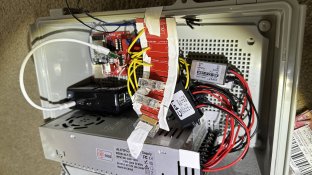
12v PSU on the left, 12V to 5V transformers on the bottom, 8A/5A fuses on the top (8A fuse on the 5V/5A converter and 4A fuse on the 5V/3A converter). DC+ path is PSU -> converter -> fuse -> 12/14awg cable to lights. DC- path is PSU -> 12/14awg cable to lights.
Electrical tape on the box is location of PG13.5 cable glands (Leftmost one is for AC power in, cable pictured bottom left), the rest are DC 5V out (two are 5A, 3 are 3A, two of the 3A’s will have two cables each)
If that was confusing, each line is a cable gland:
AC in (AC power cord)
DC 5v5A out (12 awg)
DC 5v5A out (12 awg)
DC 5v3A out (12 awg)
Two DC 5v3A out (2x 14 awg)
Two DC 5v3A out (2x 14 awg)
Will waterproof cable glands with silicone tape (As the 12/14awg wire is flat not round, and two cables in one gland would leave a gap)

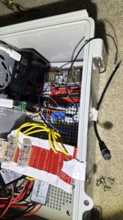
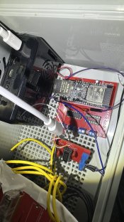
Black box is raspberry pi, connected to board that will have 2 outputs. Also have WT32-ETH01 board with 4 outputs (6 outputs total). Will connect the pigtales (Pictured, taped to outside of box) to the blue cable connectors (Cannot figure out what they are actually called lol). These will go out the side of the box in the cable gland, three pigtales per gland (2 glands total), waterproofed with silicone tape.
Some more pictures:


Some other questions:
- Since I have the cheap buck converters, are the fuses necessary? If they are, are they in the correct spot, and have the correct value? (I’m thinking it should be a 5A fuses on the 5V5A converter and 3A fuse on the 5V3A converter, but would like some confirmation if possible)
- Is it a problem routing the data cables out of the side? The box will be placed under a windowsill and will be protected from most rain if that makes a difference. I can also go overboard with the silicone tape
- Is the box too crowded? The lid does close and latch, but I believe there is very minimal clearance between the top of the power supply unit and the bottom of the box’s lid.
If you need more information/images/description, or if something I said was incorrect, confusing, or concerning, please let me know!
Thank you!
I’ve had my power supply and controller (pi4) in a non-waterproof box for my initial testing and buying-more-stuff phase, but hoping to maybe have a small show this year, which means everything needs to be outside and waterproof. I bought an electrical box that I thought everything would fit in, but it looks a little cramped once everything is actually inside.
Please ignore the mess of electrical tape. If this setup works, I’ll be 3D printing some ‘shelves’ and brackets to hold everything together (The tape is just for visualization purposes).

12v PSU on the left, 12V to 5V transformers on the bottom, 8A/5A fuses on the top (8A fuse on the 5V/5A converter and 4A fuse on the 5V/3A converter). DC+ path is PSU -> converter -> fuse -> 12/14awg cable to lights. DC- path is PSU -> 12/14awg cable to lights.
Electrical tape on the box is location of PG13.5 cable glands (Leftmost one is for AC power in, cable pictured bottom left), the rest are DC 5V out (two are 5A, 3 are 3A, two of the 3A’s will have two cables each)
If that was confusing, each line is a cable gland:
AC in (AC power cord)
DC 5v5A out (12 awg)
DC 5v5A out (12 awg)
DC 5v3A out (12 awg)
Two DC 5v3A out (2x 14 awg)
Two DC 5v3A out (2x 14 awg)
Will waterproof cable glands with silicone tape (As the 12/14awg wire is flat not round, and two cables in one gland would leave a gap)

Black box is raspberry pi, connected to board that will have 2 outputs. Also have WT32-ETH01 board with 4 outputs (6 outputs total). Will connect the pigtales (Pictured, taped to outside of box) to the blue cable connectors (Cannot figure out what they are actually called lol). These will go out the side of the box in the cable gland, three pigtales per gland (2 glands total), waterproofed with silicone tape.
Some more pictures:


Some other questions:
- Since I have the cheap buck converters, are the fuses necessary? If they are, are they in the correct spot, and have the correct value? (I’m thinking it should be a 5A fuses on the 5V5A converter and 3A fuse on the 5V3A converter, but would like some confirmation if possible)
- Is it a problem routing the data cables out of the side? The box will be placed under a windowsill and will be protected from most rain if that makes a difference. I can also go overboard with the silicone tape
- Is the box too crowded? The lid does close and latch, but I believe there is very minimal clearance between the top of the power supply unit and the bottom of the box’s lid.
If you need more information/images/description, or if something I said was incorrect, confusing, or concerning, please let me know!
Thank you!

