Difficulties setting up P5 Panel

kmw25

New elf
Joined
Jul 22, 2022
Messages
10
Location
Adelaide
Hi everyone,

I'm trying to set up a single P5 panel. I have the Hanson rPi-MFC on a Raspberry Pi 3b+ going to THIS P5 panel.

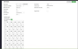
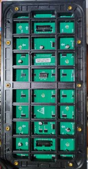
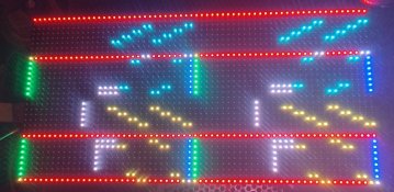
I believe I've configure everything on FPP correctly, but when I run the test pattern, everything is scrambled. Pics below of my config and of what I'm seeing on the panel. Any pointers would be great.
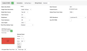
Screenshot 2025-06-28 at 23.28.17.png

IMG_20250628_232729481_HDR.jpg
 
Try these settings that I puzzled out for my P5's. It's been on my to do list to document this on the product page to save people having to puzzle it out.
P5 panel fpp setup Untitled.jpg
 
Hi everyone,

I'm trying to set up a single P5 panel. I have the Hanson rPi-MFC on a Raspberry Pi 3b+ going to THIS P5 panel.

I believe I've configure everything on FPP correctly, but when I run the test pattern, everything is scrambled. Pics below of my config and of what I'm seeing on the panel. Any pointers would be great.

View attachment 29202

View attachment 29203
I would say to check your start channel
 
I would suggest either Panel Interleave or Panel Row Address Type need playing with.
It's appears that it's doing bits of each as it goes down.
 
Hi guys,

So, checked start channel and that was correct. Tried all combinations of Panel Interleave and Row Address Type, to no avail.

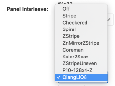
@AAH, I tried to copy your config as best I could, but my panel is 1/8 scan. Even when I tried to set it to 1/16, I didn't get the same interleave options you had. This is everything I had available:

Screenshot 2025-06-30 at 21.12.41.png Screenshot 2025-06-30 at 21.12.50.png

So still a bit stumped, really.

While changing these options did change the output, the test pattern was still jumbled, just jumbled differently.
 
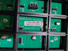
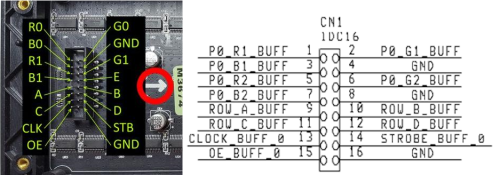
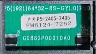
Can you shoot up a picture of the labeling on the data connector. A picture showing the panel model number sometimes can help as it will often have some of the scan details etc as part of the code.
 
The github may have shown your problem
The pics of the panel on github show that address line E is used (pin 8). On the rpi-mfc that address line isn't used. That is the address line for 1/16 scan.
It's been on my to do list for a while to do a revised rpi-mfc (and rpi-p10) to suit the 1/16th scan panels that are becoming far more common.
1751461581770.png
 
Uh.. No. The E line is for 1/32 scan panels. 1/16 scan panels only need A-D. Besides, this panel is a 1/8 scan.

They will need to play with the interleave settings and see if one works. However, the options available for the Pi for that are more limited than what are available on the Beagles. In general, driving panels directly from the Pi's isn't a great idea. Very limited options, generally bad refresh/flicker, poor support. Going with a beagle is generally a lot better. Colorlights of course can drive them fine, but that's way more complex to setup.
 
I must not post late at night. Not only can't I count but I can't read as well. I asked for a pic of the panels as it will often contain scan info. That pic contained the info but I couldn't read it it seems.
P5(1921)64*32-8S-GY1.0
P5 panel
64x32 resolution
1/8 scan
DOH.
ABCD is 4 bits (16 addresses/scans). ABCD is 5 bits (32 addresses/scans)

1751507453253.png
 
Back
Top