justinj
Apprentice elf
Just thought I'd post the following response I got from Ed relating to setting up the ECG-P12R due to the lack of manual at present:
I’m working on updating the PIXAD8 documentation to include the P12R since they are virtually the same design just different number of strings and layout. If you haven’t already done so please download and read the PIXAD8 manual from our download section.
There are logical/simple differences in the grouping of the pixel strings. PIXAD8 has two groups of 4 for power and round robin. P12R has two groups of 6 for power and 3 groups of 4 for round robin. Of course all configuration and info screens have increased from 8 to 12.
The one BIG difference is in the power configuration area.
PIXAD8 uses three little jumpers as described in the manual.
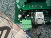
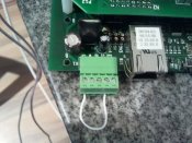
P12R uses a 3.5mm 5 pin pluggable terminal strip. It is called K1 and is located in the corner of the board next to the RJ45 connector.
From the rear K1 pinout is:
1 – V+, a connection to P13 on the P12x Panel. Used to connect to the power supply for Bank 2 of the pixel strings (7-12)
2 – VI, input to the optional use 7-36V -> 5V onboard regulator
3 – VO, output from the optional use 7-36V -> 5V onboard regulator
4 - +5, power input for the logic circuits
5 – GND, common power and signal ground
These are marked on the silkscreen legend. This allows flexible power connection to the board. You can power in several different ways.
Select one of the following:
If P13 is provided with a regulated 5VDC power supply: connect pin 1 to pin 4 (+V to +5)
If P13 is provided with 7-36VDC: connect pin 1 to pin 2 (+V to VI) and pin 3 to pin 4 (VO to +5)
If you want to provide a separate 5VDC power supply for the logic: connect +5VDC to pin 4 (+5) and GND to pin 5 (GND)
If you want to provide a separate 7-36VDC power supply for the logic: connect +7-36VDC to pin 2 (VI)and GND to pin 5 (GND), also connect pin 3 to pin 4 (VO to +5)
Please note the arrangement of the P01-P12 sockets on the panel board. They are arranged in a W pattern. Down column 1, up column 2, down column 3, up column 4. Each socket is labeled. All sockets use the same pinout but half of them are laid out oriented 180 degrees different. The pinout is our standard as described in the PIXAD8 documentation and is also on the silkscreen legend for the bottom row of sockets for reference.
ERRATA: the fuse holders for each pixel string are in the same W pattern. However the silkscreen was left incorrectly as a simple top down set of columns. The fuse holders F04 and F06 are labeled incorrectly, also F10 and F12. They should be thought of as exchanged and match the P04, P06, P10, P12 order of numbering.
I’ll post the updated manual and more information shortly.
-Ed


