How does voltage drop affect the data line?

aplant92

Full time elf
Joined
Nov 24, 2016
Messages
146
Location
Melbourne
As per the title, I always see voltage drop being talked about around the power going to the pixels, but no real mention of the data line.

I'm assuming eventually the length of cable leading to pixels will become an issue with the data line, but at what point is this? And is there any way to inject power into the data line to be able to run a larger distance from the controller?
 

darylc

404 darylc not found
Joined
Dec 8, 2012
Messages
1,146
It's not as simple as injecting power into the data line - you would corrupt the data. You'd need a null pixel to repeat the data or any of the various products the vendors sell to repeat or amplify the data. Remember the other leg of the data is the ground wire, so make sure you aren't getting much voltage drop along the ground wire. This is why people recommend using 2 wires in a 4 core cable (for example) for ground when using 3 wire pixels.
 

aplant92

Full time elf
Joined
Nov 24, 2016
Messages
146
Location
Melbourne
Ok great that makes sense - is there a general recommendation for how far away the first pixel can be from a controller in terms of ensuring the data is fed through properly?
 

darylc

404 darylc not found
Joined
Dec 8, 2012
Messages
1,146
too many variables (controller model, size of cables, power draw through those cables, interference, etc etc etc) to give general rules of thumb for distance to first pixel.
 

AAH

I love blinky lights :)
Community project designer
Joined
Dec 27, 2010
Messages
4,190
Location
Eaglehawk
Ok great that makes sense - is there a general recommendation for how far away the first pixel can be from a controller in terms of ensuring the data is fed through properly?
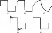
It actually depends on the controller as well as the cable. Most controllers should do 10m+ these days. J1Sys controllers which are virtually obsolete now were more like 3-5m. Pixel to pixel distance is typically maxed out around the 5m mark. There's a video on the bottom of http://www.hansonelectronics.com.au/product/null/ that shows the difference between what you can get with pixel to pixel distance with and without a buffer. The same applies when/if you have distance issues from a controller. Unlike the need for power injection like occurs with pixels with data it's actually the rounding of the signal due to cable capacitance that is the limiting factor. The further the data has to travel the less like the original square wave it started as it looks like. The voltage does go down but it's not due to lack of voltage. The pixel cable is both resistive (which is why you need power injection) and capacitive. The effect of the 2 changes the shape and voltage. See the attached pic. The data signal starts off like a) and progressively gets more like c) but unlike in the picture the voltage reduces.
 

Attachments

  • square-wave.jpg
    square-wave.jpg
    13.8 KB · Views: 17

aplant92

Full time elf
Joined
Nov 24, 2016
Messages
146
Location
Melbourne
It actually depends on the controller as well as the cable. Most controllers should do 10m+ these days. J1Sys controllers which are virtually obsolete now were more like 3-5m. Pixel to pixel distance is typically maxed out around the 5m mark. There's a video on the bottom of http://www.hansonelectronics.com.au/product/null/ that shows the difference between what you can get with pixel to pixel distance with and without a buffer. The same applies when/if you have distance issues from a controller. Unlike the need for power injection like occurs with pixels with data it's actually the rounding of the signal due to cable capacitance that is the limiting factor. The further the data has to travel the less like the original square wave it started as it looks like. The voltage does go down but it's not due to lack of voltage. The pixel cable is both resistive (which is why you need power injection) and capacitive. The effect of the 2 changes the shape and voltage. See the attached pic. The data signal starts off like a) and progressively gets more like c) but unlike in the picture the voltage reduces.
That's a great explanation - thanks, and the video is also great for illustrating the effects! It's good to know things like that buffer exist too - I take it they just allow you to run longer distances between the controller and first pixel/pixel to pixel?
 

AAH

I love blinky lights :)
Community project designer
Joined
Dec 27, 2010
Messages
4,190
Location
Eaglehawk
That's a great explanation - thanks, and the video is also great for illustrating the effects! It's good to know things like that buffer exist too - I take it they just allow you to run longer distances between the controller and first pixel/pixel to pixel?
They allow the distance between any 2 pixel "things" to be extended. If you need to go further than what 1 will go you can add a 2nd, 3rd, 4th. I had someone tell me that they went to 170m the other day before they ran out of cables on hand. I thought 33m that I got was a good effort. Not sure how many nulls were added to get 170m but it's a BIG number for non differential pixel transmission.
 

aplant92

Full time elf
Joined
Nov 24, 2016
Messages
146
Location
Melbourne
They allow the distance between any 2 pixel "things" to be extended. If you need to go further than what 1 will go you can add a 2nd, 3rd, 4th. I had someone tell me that they went to 170m the other day before they ran out of cables on hand. I thought 33m that I got was a good effort. Not sure how many nulls were added to get 170m but it's a BIG number for non differential pixel transmission.
Ok cool!

Out of curiosity - how do the null pixels allow the distance to be boosted so drastically? Are they amplifying the data signal or something similar?
 

David_AVD

Grandpa Elf
Community project designer
Generous elf
Joined
Jun 12, 2010
Messages
4,681
Location
Victoria Point (Brisbane)
The null pixels / signal buffers accept the slightly degraded signal in and regenerate a fresh clean signal out. So as long as they are put inline before the signal gets too badly affected they will work well.
 

AAH

I love blinky lights :)
Community project designer
Joined
Dec 27, 2010
Messages
4,190
Location
Eaglehawk
A standard pixel inserted into the line will regenerate the signal and go an extra x metres. The difference between a pixel and a buffer is the ability to drive a square wave signal into a capacitive cable. Referring back the that square wave picture what you are seeing is the effect of an RC (resistor capacitor) curve. The capacitance is from the length of cable and increases the longer the cable is. The resistance comes from 2 sources. It comes from the very low resistance of the cable (it has to be low to allow amps of current to power pixels) and the internal resistance of the IC that is driving the cable. Pixel chips have a fairly high source resistance / low drive current which is 1 of the major limiting factors in how far they can be separated. The chips that I chose for the buffer were specifically chosen because they have a high drive current. This means that the shape of the square wave data signal remains squarer for longer. Other sneaky stuff in the design is there to reduce the ringing as seen as in d) and e) of the picture.
 

Kredal

New elf
Joined
Nov 27, 2018
Messages
1
If I have a 15 meter cable run to a set of strips with 30/10 LEDs with WS2811 chips, can I use a 2811 bullet as the null pixel halfway down the line? Or does it have to be exactly the same type of pixels to regenerate the signal? (Of course, I haven't actually tested this run yet, and it *might* be fine. I'll find out this afternoon, hopefully!)
 
This thread is very old. An answer might not be needed anymore.
Top