Lytworx 2 wire LED strings Driver solution

shraps

New elf
Joined
Jan 23, 2014
Messages
11
Location
Tamworth NSW
Hello Aus Christmas Lighting


I have developed a LED string driver for the Bunnings Lytworx and other brands that use an AC signal to drive the LEDs


As per the post by AAH about the lytworx LED strings from bunnings http://auschristmaslighting.com/forums/index.php?topic=6367.msg56786#msg56786 there is the delay for turning on the lamps with a normal ACSSR controller can be up to 1 second.


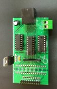
I have designed and currently testing a 8 channel driver card enough for 4 Strings of LEDs.


unfortunately it will not be ready for this year


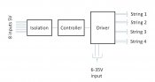
It can be driven by any standard 5v output through a optoisolator, microcontroller to generate the AC signal and output to the lights with a H bridge driver.
This would allow the output of a standard controller to drive the low voltage AC strings with no delay.


preliminary cost of the unit would be $30 assembled


Pictures coming soon
 

shraps

New elf
Joined
Jan 23, 2014
Messages
11
Location
Tamworth NSW
here is a photo of the prototype without the opto isolation installed


Any Interest?
 

Attachments

  • light driver.jpg
    light driver.jpg
    680.4 KB · Views: 64

BundyRoy

Dedicated elf
Joined
Apr 9, 2014
Messages
1,026
I've been hoping someone would do this Shraps. Let me see if I've got this right. I just power the board with a 5V DC power supply. It accepts DMX input from my controller to control the channels.

Is it 2 channels per string. Can the strings be made to twinkle or are they limited to either on/off and maybe dimming.

All my lights is 12V. Is it possible to drive it with a 12V power supply. I know I can use a DC-DC convertor if needed.

Thanks

Roy
 

AAH

I love blinky lights :)
Community project designer
Joined
Dec 27, 2010
Messages
4,188
Location
Eaglehawk
Any chance of a connection diagram of how it would connect up shraps. At this point I'm guessing that the input from the 8 DC channels of a dimmer go into the SIL strip, power for the output strings goes into X34 and I imagine that's an RJ45 connector X41. What I can't figure out is how the 16 connections for the 8 strings get out of the board as an RJ45 plug only has 8 connections.
Also will this handle 31V which is what most Big W type strings seem to use.
 

lizardking

IT IS STILL ALL BENS FAULT
Joined
Dec 26, 2014
Messages
416
Location
Gold Coast
lots
shraps said:
here is a photo of the prototype without the opto isolation installed


Any Interest?
lots of interest from here i am looking a net lights for next year keep us informed please
 

shraps

New elf
Joined
Jan 23, 2014
Messages
11
Location
Tamworth NSW
Hi all

to answer your questions below is a block diagram of how it works. at the moment input is 10 pin plug and output is RJ45 (2 pins per LED string)

there are 8 inputs that will drive the 2 wire string lights hence 4 sets of strings.

Output drivers are rated to 36V using H bridge with output current 1A continuous so you could drive several strings per output. or lower the voltage and cut strings in half (I have successfully driven 31V strings at 12V by cutting into thirds)

Opto isolation used so that independent power supply (including step up) will not impact controller

[/size][SIZE=small]If the input is PWM then you should be able to dim it.[/SIZE]


[/size]I have not been able to properly test it under a sequencing situation also what connectors would you like to see on the controller?input - RJ45, molex pinoutput RJ45, screw terminal[size=small]
 

Attachments

  • output driver.JPG
    output driver.JPG
    33.9 KB · Views: 48

lizardking

IT IS STILL ALL BENS FAULT
Joined
Dec 26, 2014
Messages
416
Location
Gold Coast
][/size]I have not been able to properly test it under a sequencing situation [/size]also what connectors would you like to see on the controller?[/size]input - RJ45, molex pin[/size]output RJ45, screw terminal
[/size]i have not a clue what else you just said but screw terminals and a rj45 connector would be handy
[/size]no i have no idea on dmx but yes i am still interested
[/size]
 

diyer

Full time elf
Joined
Jan 5, 2013
Messages
149
Location
Sunbury
Great work shraps,
I'm not too concerned about the connections, it's easy to work around any configuration, plus add a couple of mounting holes
Do you have any video of the unit in operation?
 

Pesle

New elf
Joined
Dec 10, 2017
Messages
12
Location
Newcastle
Ive made something similar last year with just an arduino and some motor controllers (h bridges) like what you have. This year im taking it a step further and adding ethernet and E1.31 support to it so i can hopefully have all computer controlled christmas lights this year. I have also run into an issue where i cannot get both channels to dim different values on one string. It could just be a timing thing, but i just got alot of flicker, so ive "solved" this by making it accept either string on at a time, or both on with the brightness of the first channel which seems to work fine. Ive also added a rectifier circuit to my design so that i can use old 24V ac power adapters to get 30V+ DC to run the lights without needing to modify them.
 

AAH

I love blinky lights :)
Community project designer
Joined
Dec 27, 2010
Messages
4,188
Location
Eaglehawk
On my DMX2-18 I use a Pic16F1823 and some logic. One of the most important steps is the gating at 50% duty cycle of the 2 halves of the waveform. The gating probably should be around 50Hz to be a balance between flicker and affecting the pwm for the 2 polarities.
 
Top