Derf
am now a 5v hypocrite
Hi All,
As this is has been a common question recently I thought I would write up a quick how to guide on how I got my 5x6 p5 panel matrix up and running.
Please click spoiler buttons to reveal images.
End Result:
[A] My Setup:
First of all just some basic information about my setup. This panel is running the following:
[B.] Hardware Setup]
Think of the configuration of these panels as two separate matrix's sat next to each other. Each Colorlight card is identified as a separate "Screen" in the LED vision software.
Once your screen is wired and you have your two LED vision cards daisy chained with ethernet cables go a head and download and install LED vision: http://www.colorlight-led.com/download/Colorlight_LEDVISION_5_0_Setup.html
Ensure it is version 5 as there can be issues with other versions. (update: 2024: Colorlight locked their installers in a password zip file the password is "buyfromcolorlit"
Once installed plug an ethernet cable into a gigabit ethernet port in your computer (Ensure its gigabit else wise use the USB to ethernet adapter linked earlier) connect the other side into the first card in the daisy chain.
[C] Adjust to Suit your Screen
Before we proceed we need a bit of info regarding our screen. For simplicity of this write up we will refer to the following
Total Screen Size: All screen Pixels in the final matrix (in my case this would be 320 Pixels Wide and 192 High.) 320x192
Screen 1 Size: Pixel dimension in the first card. (in my case this would be 192 Pixels Wide and 192 High)
Screen 2 Size: Pixel dimension on the second card. (in my case this would be 128 Pixels Wide and 192 High).
Now its time to configure the screen in LED vision.
[D] LED Vision Setup
Step 1.
First things first. We need to set the test screen on LED vision to the correct dimension for testing.
Up the top click on Screen -> Screen Management.
As we want the screen to be a single matrix in the end we want to ensure down the bottom we have 1 screen count.
We change our Width and Height to our Total Screen Size: Width: 320, Height: 192
Click Apply.
Step 2.
Following setting our test screen we need to start configuring the receiver cards to let them identify the type of panel we are using. (In my case Lysons P5 LED Panel).
From the last screen click the LED Screen Setting and enter password 168.
Ensure the screens are plugged in and on the right hand side of the Sending device tab attempt to scan for your cards. You should see 2 line items one for each card.
Step 3.
Following the previous step navigate to the screen parameters tab.
This is were we tell the Total combined cards (2 Cards) the overal sizing and panels being used. (At this point of time you cannot mix and match panel types).
When you purchase your panels from a manufacturer or supplier as for the colorlight / LED vision configuration file specific for the purchased panels. In the case of lyson's panel I requested this file through a sales rep and was sent the file. For anyone using the panel you can download this configuration file here: http://share.jacks.tools/download/f41df82632a7f7ff4f2acfb4c0f04e62.html
Click the load button and navigate for your configuration file.
(If you do not have this file you can select a configuration preset from within this screen parameters page.)
Once the configuration file has been uploaded change your "Box Setting to reflect your Total Screen Size. (E.g Width: 320 Height: 192)
Once completed you must click the "Save to Receiver" button.
Step 4.
After configuring the Screen parameters we now are required to setup the "Receiver Mapping (Look From Front)" tab.
Now this is where in my opinion it got confusion and weird. As I had to create the link backwards.
For my configuration two separate vertical screens (Screen 1, Screen 2) I had to change the Col Count to 2.
You then are required to click a panel you want to configure for example in the grid of panels in the grey area Column 1, Row 1. Once clicked it becomes active to edit. You then configure the Screen 1 Size on the right hand side as per the below.
You then do the same for the second screen clicking on it first to make it active which changes it to No.2. Mine are configured as per the following:
Once completed you have to draw the wiring direction. In my panel instance I had to select the backwards wiring option. This is the button on the grid of circles and arrows down the bottom right of the screen window. 2 down, second across. Once selected select the panels starting from the right to the left this will overlay a Start (S) and End (E) over the panel grid.
Once completed Click "Save to Receiver".
IMPORTANT: ENSURE YOU HAVE CLICK SAVE TO RECEIVER ON BOTH THE SCREEN PARAMETERS AND RECEIVER MAPPING TABS. IT DOES NOT SAVE BOTH SCREEN SETTINGS.
You should now have an output to your Matrix that looks identical to the LED test pattern that has on the top left hand side of your computer screen. (You can also drag your mouse over this and it should reflect on the matrix).
[E] Installing Falcon Pi Player onto a Raspberry Pi
FPP 3.2
For everyone out there that requires assistance with installing falcon pi player to a raspberry pi here is a quick how to guide.
Download the following:
1. Etcher (Burns FPP image to a removable micro SD card) https://www.balena.io/etcher/
2. Latest Version of Falcon Pi Player: https://github.com/FalconChristmas/fpp/releases (download the latest FPP-V*.*-Pi.img.zip
Step 1:
Take a Microsd Card (Minimum 4GB) and insert into a MicroSD to USB converter: https://www.ebay.com.au/itm/Micro-S...H-SDHC-MINI-ADAPTER-32GB-64GB-16/332582425783
Step 2:
Open Etcher and click Select Image.
Navigate to your FPP-V*.*-PI.img.zip which should be in your downloads folder.
Ensure the correct sized media is select (SD Card)
Press Flash.
Step 3:
When the image has been written to the SD card take it out of your computer and plug it into your Raspberry Pi.
Take this time to insert your other USB to Ethernet Adapter and plug the onboard raspberry pi ethernet to your home network / internet / modem / switch. Plug the USB to Ethernet adapter into your first Colorlight card.
Power on your Pi.
Step 4:
Wait 1-4 Minutes for the first time configuration to run.
Go to a computer connected to the same network as the PI's ethernet cable.
Assuming this is the Only Raspberry PI running FPP on your Network open your browser and navigate to http://fpp/
This should bring up Falcon PI Player's web interface.
[F] Setting Up The Matrix In Falcon Pi Player
Now that we have the p5 Panel and pi ready to go we can setup these panels in Falcon Pi Player. Now there is a couple of oddities I have found with different setups mainly to do with the orientation of the p5 matrix arrows in the led panels tab.
Step 1.
Navigate to the Input / Output Setup Tab and click on Channel Outputs.
Click on the LED Panels tab.
Select your Panel Layout Size. (In my Case (5x6)). Ensure the rest of the settings are as follows:
Step 2.
Set your panels as one continuous panel the Output numbers change differently here and a new card is not a new output port. For example in my setup the configuration is as below. (Note for my matrix all the panel direction arrows are upside down.
Run a Status / Control -> Display Testing to see if it works.
I the above helps with configuring your panels. This did take some trial and error to discover why the panels did some weird stuff.
Thanks all
Derf | Jack
As this is has been a common question recently I thought I would write up a quick how to guide on how I got my 5x6 p5 panel matrix up and running.
Please click spoiler buttons to reveal images.
End Result:
Spoiler content hidden. Log in to see this content.
[A] My Setup:
First of all just some basic information about my setup. This panel is running the following:
- 30 p5 panels from Lyson LED - https://www.aliexpress.com/item/32828066311.html
- 3D Printed Brackets designed by Lithgow Lights, Printed in ABS by Ben.
- 2x Colorlight 5a-75B - https://www.aliexpress.com/item/32331955683.html?spm=2114.12010612.8148356.3.298c4bcfTgbrvl (Currently only 2 can be connected to FPP)
- 2x Raywell's 5v 350W (60A)
- Raspberry PI 3 Model B+
- USB 3.0 to Gigabit RJ45 Ethernet adapter - https://www.ebay.com.au/itm/USB-3-0-to-Gigabit-RJ45-Ethernet-LAN-Network-Adapter-1000Mbps-For-PC-Laptop-Mac/401008027970?ssPageName=STRK:MEBIDX:IT&_trksid=p2060353.m2749.l2649 (NOTE COLORLIGHT CARDS REQUIRE A GIGABIT ETHERNET PORT TO FUNCTION)
- 2.5mm2 Cable
Spoiler content hidden. Log in to see this content.
[B.] Hardware Setup]
Think of the configuration of these panels as two separate matrix's sat next to each other. Each Colorlight card is identified as a separate "Screen" in the LED vision software.
Once your screen is wired and you have your two LED vision cards daisy chained with ethernet cables go a head and download and install LED vision: http://www.colorlight-led.com/download/Colorlight_LEDVISION_5_0_Setup.html
Ensure it is version 5 as there can be issues with other versions. (update: 2024: Colorlight locked their installers in a password zip file the password is "buyfromcolorlit"
Once installed plug an ethernet cable into a gigabit ethernet port in your computer (Ensure its gigabit else wise use the USB to ethernet adapter linked earlier) connect the other side into the first card in the daisy chain.
[C] Adjust to Suit your Screen
Before we proceed we need a bit of info regarding our screen. For simplicity of this write up we will refer to the following
Total Screen Size: All screen Pixels in the final matrix (in my case this would be 320 Pixels Wide and 192 High.) 320x192
Screen 1 Size: Pixel dimension in the first card. (in my case this would be 192 Pixels Wide and 192 High)
Screen 2 Size: Pixel dimension on the second card. (in my case this would be 128 Pixels Wide and 192 High).
Now its time to configure the screen in LED vision.
[D] LED Vision Setup
Step 1.
First things first. We need to set the test screen on LED vision to the correct dimension for testing.
Up the top click on Screen -> Screen Management.
As we want the screen to be a single matrix in the end we want to ensure down the bottom we have 1 screen count.
We change our Width and Height to our Total Screen Size: Width: 320, Height: 192
Click Apply.
Spoiler content hidden. Log in to see this content.
Step 2.
Following setting our test screen we need to start configuring the receiver cards to let them identify the type of panel we are using. (In my case Lysons P5 LED Panel).
From the last screen click the LED Screen Setting and enter password 168.
Ensure the screens are plugged in and on the right hand side of the Sending device tab attempt to scan for your cards. You should see 2 line items one for each card.
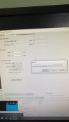
Step 3.
Following the previous step navigate to the screen parameters tab.
This is were we tell the Total combined cards (2 Cards) the overal sizing and panels being used. (At this point of time you cannot mix and match panel types).
When you purchase your panels from a manufacturer or supplier as for the colorlight / LED vision configuration file specific for the purchased panels. In the case of lyson's panel I requested this file through a sales rep and was sent the file. For anyone using the panel you can download this configuration file here: http://share.jacks.tools/download/f41df82632a7f7ff4f2acfb4c0f04e62.html
Click the load button and navigate for your configuration file.
(If you do not have this file you can select a configuration preset from within this screen parameters page.)
Once the configuration file has been uploaded change your "Box Setting to reflect your Total Screen Size. (E.g Width: 320 Height: 192)
Once completed you must click the "Save to Receiver" button.
Spoiler content hidden. Log in to see this content.
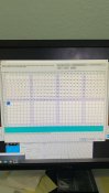
Step 4.
After configuring the Screen parameters we now are required to setup the "Receiver Mapping (Look From Front)" tab.
Now this is where in my opinion it got confusion and weird. As I had to create the link backwards.
For my configuration two separate vertical screens (Screen 1, Screen 2) I had to change the Col Count to 2.
You then are required to click a panel you want to configure for example in the grid of panels in the grey area Column 1, Row 1. Once clicked it becomes active to edit. You then configure the Screen 1 Size on the right hand side as per the below.
- No. 1 -- This is the Physical Colorlight Card in the Chain Number
- Width 128
- Height 192
You then do the same for the second screen clicking on it first to make it active which changes it to No.2. Mine are configured as per the following:
- No. 2 -- This is the Physical Colorlight Card in the Chain Number
- Width 192
- Height 192
Once completed you have to draw the wiring direction. In my panel instance I had to select the backwards wiring option. This is the button on the grid of circles and arrows down the bottom right of the screen window. 2 down, second across. Once selected select the panels starting from the right to the left this will overlay a Start (S) and End (E) over the panel grid.
Once completed Click "Save to Receiver".
Spoiler content hidden. Log in to see this content.
You should now have an output to your Matrix that looks identical to the LED test pattern that has on the top left hand side of your computer screen. (You can also drag your mouse over this and it should reflect on the matrix).
Spoiler content hidden. Log in to see this content.
[E] Installing Falcon Pi Player onto a Raspberry Pi
FPP 3.2
For everyone out there that requires assistance with installing falcon pi player to a raspberry pi here is a quick how to guide.
Download the following:
1. Etcher (Burns FPP image to a removable micro SD card) https://www.balena.io/etcher/
2. Latest Version of Falcon Pi Player: https://github.com/FalconChristmas/fpp/releases (download the latest FPP-V*.*-Pi.img.zip
Step 1:
Take a Microsd Card (Minimum 4GB) and insert into a MicroSD to USB converter: https://www.ebay.com.au/itm/Micro-S...H-SDHC-MINI-ADAPTER-32GB-64GB-16/332582425783
Step 2:
Open Etcher and click Select Image.
Navigate to your FPP-V*.*-PI.img.zip which should be in your downloads folder.
Ensure the correct sized media is select (SD Card)
Press Flash.
Step 3:
When the image has been written to the SD card take it out of your computer and plug it into your Raspberry Pi.
Take this time to insert your other USB to Ethernet Adapter and plug the onboard raspberry pi ethernet to your home network / internet / modem / switch. Plug the USB to Ethernet adapter into your first Colorlight card.
Power on your Pi.
Step 4:
Wait 1-4 Minutes for the first time configuration to run.
Go to a computer connected to the same network as the PI's ethernet cable.
Assuming this is the Only Raspberry PI running FPP on your Network open your browser and navigate to http://fpp/
This should bring up Falcon PI Player's web interface.
[F] Setting Up The Matrix In Falcon Pi Player
Now that we have the p5 Panel and pi ready to go we can setup these panels in Falcon Pi Player. Now there is a couple of oddities I have found with different setups mainly to do with the orientation of the p5 matrix arrows in the led panels tab.
Step 1.
Navigate to the Input / Output Setup Tab and click on Channel Outputs.
Click on the LED Panels tab.
Select your Panel Layout Size. (In my Case (5x6)). Ensure the rest of the settings are as follows:
- Enable LED Panel Output: (TICKED)
- Single Panel Size (WxH): 64x32
- Model Start Corner: Bottom Left
- Panel Gamma: 1 or 1.8 (Change to suite your colour preference)
- Connection : ColorLight (VERY IMPORTANT)
- Start Channel: 1 (I Use DDP for my Matrix)
- Channel Count: 184320 (Calculated automatically you cannot set this)
- Default Panel Color Order: BGR
- Interface: eth0 (IT IS ETH0 IN MY CASE) this could be easily be eth1 as there is multiple ethernet adapters on the pi. Trial and error on this or use Help -> Troubleshooting Commands and find the ethernet (eth#) that has an assigned a 169.*.*.* Ip address).
Step 2.
Set your panels as one continuous panel the Output numbers change differently here and a new card is not a new output port. For example in my setup the configuration is as below. (Note for my matrix all the panel direction arrows are upside down.
Spoiler content hidden. Log in to see this content.
Run a Status / Control -> Display Testing to see if it works.
I the above helps with configuring your panels. This did take some trial and error to discover why the panels did some weird stuff.
Thanks all
Derf | Jack
Last edited:
")