p10 panels - fpp test messy

Boof63

Senior elf
Joined
Nov 7, 2011
Messages
594
Location
Kadina
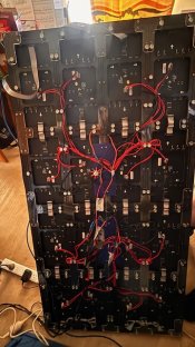
HI all,i have a matrix pf p10 panels 4 x4 , that was running of an old hinx pix controller (2015?). anyways been faulty last two years. Have now got a pihat from Hanson electronics and fpp9.3.3 running. FPP test pattern is messed up on the first row 1-4 panels and third row 9-12 (test image is reversed as per picture) and layout of the wiring.
have played with FFP LEd matrices setup but i cant unscramble the FPP test pattern.
1. do i need to physically flip the panels in the reversed images - (hoping not for this)
2. is it a hardware problem ie piHat driving 8 panels per output, seems to run test coloure ets from FPP fine.
3. is it a software problem that can fix my problem
4 am i stuck?
cheers and thanks for any help offered
regards Ianfpp p10 matrix setup.PNGfpp setup 1.PNGIMG_0855.jpg
img_0856-jpg.30149
 

Attachments

  • IMG_0856.jpg
    IMG_0856.jpg
    221.4 KB · Views: 101
Your issue looks to be the interpretation of what the arrows mean. They are an indicator of the "up" direction of the panels. You've put the arrows as if that's the wiring direction but that's taken care of through the O1P1, O1P2 etc.
1763542338918.png
 
that made it better Alan, in that each test pattern is aligned within each panel, but row 1 & 3 are still 180 degrees out of sync and reversed compared with row 2 & 4 as per picture previous. ANy thoughts please?
 
Last edited:
ANy thoughts please?
Mine (3Hx4W) I have all the arrows on the panels pointing the same direction. Ie. Left and down, then set FPP to the same or mirrored (eg. Right and down). From AAH pihat wired o1 to TopLH, o2 to MidLH, and o3 to BotLH and all other panels connected horizontally
 
that made it better Alan, in that each test pattern is aligned within each panel, but row 1 & 3 are still 180 degrees out of sync and reversed compared with row 2 & 4 as per picture previous. ANy thoughts please?
I need pics of fpp panel layout and result to have any idea.
 
Look closely at how the panels are laid out and they arrow changes and make sure the arrows in fpp match the way the arrows on the physical panels go. AHH inverted the arrows to the panels, it looks like the top point down and the 2nd row point and it keeps to that pattern.
 
Hi team, i have flipped the actual panels 1 & 2- 180 degrees, this now displays the Fpp test pattern in the correct alignment, Problem is i would now be starting the top row of panels (1 to 4) from the left hand side (back view) not rhight hand side as normally suggested and panels 5-8 from the right hand side as well, mayne i just need a long ide cable to reach from panel 4 to 5? would thjis solve my problem. Also can some one show me their node layout from their matrix in xlights -just to make sure im still heading in the right direction please.

1->2->3->4->
[--------------]
5->6->7->8

cheers and thanks for the input
PS i cant have them all pointing in same direction as running 8 panels from one PIHat output so orginally as shown in picture 9this was same alignement as old Hinckspix controller - 2 outputs x 8 panels]
- ⬆️⬆️⬆️⬆️ - input 1
[ - ⬇️⬇️⬇️⬇️- ends
- ⬆️⬆️⬆️⬆️- input 2
[ - ⬆️⬆️⬆️⬆️ - ends

do i need to rethink my whole alignment ie all arrows pointing up seems to be an option with 180o rotation of actual panels 1&2?
 
here is rotated panels 1&2 back and fpp test, only panels 1&2 connected hence odd lights and black on panels 5-8
cheers and again thanks for yout help and patience :)
Boof
IMG_0857.jpgIMG_0858.jpgIMG_0859.jpg
 
My brain is too mushy at this time of year to process much.
On the final picture if you flip the arrows around 180 degrees for panels 2-1, 2-2, 2-3 and 2-4 that should fix that issue. You do have to do a fppd restart after saving.
A heads up on a potential issue that may not occur. I have seen data corruption from sequential panels not having their power come from the pair of red and black power cables. In your case I don't imagine that it's a problem as all of the cables are going back to the same point. And that brings me to my next warning. I can't really tell what cable size is in use but for 16 panels at a guesstimated 2A max current each I would suggest that at least 2.5mm2 cable is used from the power supply to your distro point.
 
setup has been same for 8 years, no power problems or hot wiring, but understand concerns, if i flip panels then starting corners will be left hand side viewed from back, not RHS, .wont his screw up any data from xlights. As xlights model is still same node layout as before change of hardware?
 
think i may ahve worked it out, my matrix starts top right (looking from the back ) i think i need to realign the panels (obviously he says to himself) however data only flows in one direction. thus setup (rear view) would be
New - O1 - p1->p2->p3->p4-
p5->p6->p7->p8
and the same for output 2
so i need a 2 x large ide cable 1.5m to connect from p4 to p5
cheers and hope this ,makes some sense.
my head is scrambled as well
cheers
 
  • Like
Reactions: AAH
if the above works ie all date left to right and ide cables cant be longer than 36 inches, = running two PIs=Hats for th matrix.
if so how can i daisy chain the two PIs via ethernet. data input for matrix is via F3 controller in and out, i dont have any more space on my router for another cable slot. please dont suggest wifi, tried it 8 years ago and never worked. thanks again all for the input
PS is FPP in player or remote mode if wish to run show from Xschedule and my computer?
 
A cheap 5 or 8 port switch should free up your outputs on your router.
You can run the Pi in player mode or remote mode. In remote mode all of the sequences would get sent to each of the FPP devices and your pc would pretty much just be sending out sync packets.
IF you had the Pi in player mode and wanted to send everything from the pc then the inputs and outputs would get uploaded from xlights but no playlist would get created. When you play from xlights or xscheduler the FPP devices will pop up a message saying DDP data being received and they will work essentially in the same way as what bridge mode did in years past.
I have some IDC cables longer than 36" for my matrix with no issues. It's only a P10 matrix so there's nowhere near as much data being sent as what a P5 one would need.
 
Hi Alan, thanks for reply, i need a cable IDC that is 1.4mts long, is there away to join 2-3 smaller cables or can i find one long one,
cheers
 
You should be able to go to Jaycar and buy the bits to make one
Just take a sample of what you have to make sure you get the right plugs and leads
 
Back
Top