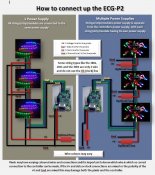
P2 setup

ShellNZ

Senior elf
Joined
Jun 17, 2012
Messages
892
Location
Karaka, Auckland, NZ
Heres my setup....

WS2811 modules, not supported by P2 yet I know but apparently will run on 180X on 2000

wiringpic1.jpg


No blinky :) Any and all help would be much appreciated :)

Top right pic is a bit small so here tis...
config9.jpg
 

ShellNZ

Senior elf
Joined
Jun 17, 2012
Messages
892
Location
Karaka, Auckland, NZ
Image taken 30mins ago of string stats
config13.jpg


Image taken just now
config15.jpg

There are packet updates now, no idea what that means but its gotta be good eh?
 

David_AVD

Grandpa Elf
Community project designer
Generous elf
Joined
Jun 12, 2010
Messages
4,681
Location
Victoria Point (Brisbane)
Sounds like you have (had) more than one issue.

With the new IP address, you at least seem to get getting the data to the P2.

Now you'll have to concentrate on the P2 - pixel side of things.
 

AAH

I love blinky lights :)
Community project designer
Joined
Dec 27, 2010
Messages
4,188
Location
Eaglehawk
At the moment the problem is that there is no power at the output pins going to the pixels. Muddling through the manual now to work out what jumper/s are required to get the 12V happening at the output.
 

fasteddy

I have C.L.A.P
Global moderator
Joined
Apr 26, 2010
Messages
6,648
Location
Albion Park NSW
AAH said:
At the moment the problem is that there is no power at the output pins going to the pixels. Muddling through the manual now to work out what jumper/s are required to get the 12V happening at the output.

The P2 does not have power +12V at the output, it has data, clock and common

The below diagram will show you how its connected

Can someone please confirm that i have the power supply to the P2 connected correcly

[attachimg=1]
 

Attachments

  • p2+wiring.JPG
    p2+wiring.JPG
    127.2 KB · Views: 160

j1sys

There are no rules, and those are the rules.
Community project designer
Joined
May 19, 2010
Messages
242
Location
Knoxville TN USA
Just want to chime in that the ECG-P2 was not designed to source/provide power to the pixels. The connections for +V on the pixel string connectors can be used for a LIMITED amount of power through the board or even use the OKI regulator to provide 5V for VERY LIMITED power (less than 1A) or can be used to backfeed the pixel power into the unit to provide power for the board.

All power to the pixels should be external to the unit. and then fuses are optional and supplied by the user.

-Ed
 

BrianJ

Full time elf
Joined
Jun 21, 2012
Messages
114
Location
Kingston, Ontario
Shell is aware of the power limitations of the P2. She is only trying to drive 1 candle as a test setup from the P2 with 15 - 2811 modules. the total power draw of this candle on full white is less than the 1 amp that the P2 should output. (Total 10.8 watts)
 

ShellNZ

Senior elf
Joined
Jun 17, 2012
Messages
892
Location
Karaka, Auckland, NZ
Thanks everyone :)

I finally got it all going, had my wiring to the P2 wrong. Thanks David for 10.10.10.10 suggestion, that got me at least seeing action in P2 config (string updates) then moved onto wiring.

Unfort once going there are some further wiring hiccups within the candles now so gotta pull some apart to figure out whats gone wrong. Bless pixels and P2 tho with RGB as unlike dumbRGB if e.g blue/green are mixed up when lights go I can just change the order within P2 config :)

Will be spending the next few days doing repair work :)
 

neilric99

Full time elf
Joined
May 20, 2010
Messages
295
Location
Irvine, the OC, CA
Shell, depending on the pixel the order of the colours can be different than R,G,B
best option is to use David_AVD's utility da_e131 to test it and then you can set the P2 config accordingly to do the correct output mapping.
 
Top