P2 vs P12R string outputs :(

BillInSoFL

Apprentice elf
Joined
Mar 12, 2012
Messages
94
Location
Hollywood, FL
Back in February-March I bought a single P12R which has 12 outputs. The outputs are Gnd, Clk, Data, +V and that's the way I've been making wiring everything and making connectors.

I recently received 2 more P12R's and 3 - P2's. I am little disappointed that the string outputs on the P2's don't match the P12R (not to mention they aren't labeled). Based on reading here in the forums P2 outputs are Gnd, Data, Clk, V+, which means I think I'm going to have to create special cables when connecting to the P2 vs. P12R.

Can someone confirm?? Are there plans to address this at some point??? I mean it's fine if you only have P2 or P12R, but when you're using as many controllers as I am you'd like everything to be interchangeable.

Also due to the somewhat shaky documentation I had some magic blue smoke some out of the OKI-7BSR5. It still seems functional although I'm only testing 12V WS2801 so we'll have to wait and see. I suppose it's good I bought 3, but it's a shame for that to happen because there isn't proper documentation :(
 
my P2's outputs I received the other day are labeled as G, C, D, V which is the same the P12R right?

BillInSoFL said:
Back in February-March I bought a single P12R which has 12 outputs. The outputs are Gnd, Clk, Data, +V and that's the way I've been making wiring everything and making connectors.

I recently received 2 more P12R's and 3 - P2's. I am little disappointed that the string outputs on the P2's don't match the P12R (not to mention they aren't labeled). Based on reading here in the forums P2 outputs are Gnd, Data, Clk, V+, which means I think I'm going to have to create special cables when connecting to the P2 vs. P12R.

Can someone confirm?? Are there plans to address this at some point??? I mean it's fine if you only have P2 or P12R, but when you're using as many controllers as I am you'd like everything to be interchangeable.

Also due to the somewhat shaky documentation I had some magic blue smoke some out of the OKI-7BSR5. It still seems functional although I'm only testing 12V WS2801 so we'll have to wait and see. I suppose it's good I bought 3, but it's a shame for that to happen because there isn't proper documentation :(
 
This is not an issue if you use the Ray Wu plugs coming out of the controller that most are using. It would only be an issue if you are using the board screw plugs to swap and change if the P12R and P2 have different data and clock orinetation. And even then its a matter of swapping 2 wires on 2 plugs of the P2 if your swapping and changing in this fashion.
I dont currently have a P2 so I cant comment, but i would believe that if they are different that this may not be an easy change as this is at the board track design level.
Im plan on eventually doing something similar to the P12R manual with the P2, but my focus is now on my display and im not sure on what documentation Ed currently has besides this one on the P2 as i dont have one at the moment, but plan to get one very soon.


So the P12R orientation is

Pin 1 - +VDC
pin 2 - Data
Pin 3 - Clock
Pin 4 - Ground


Can someone who has a P2 in hand confirm the pin outputs compared to the P12R shown above.
 
Look at the orientation face on it looks like it is different.

ECG-P2-2.jpg


p12r.jpg
 
I just confirmed the plug pin orientation is the same as the P12R as what is in the diagram of the P2 that Shell showed, so im not sure what the issue is. It may actually be an issue with the lights your testing as clock and data may be mixed and marked incorrectly which has happened before.
 
I got my p2 without a case and had nothing on the board to tell me what the outputs were. I used the diagram and it worked just fine.
 
The P2 case may be labeled but the board is not. I got boards since they are going in enclosures anyway. Power inputs aren't labeled nor are the string outputs :( P2 ECG-D2 Quick Notes.pdf doesn't detail hooking up power or what the pin layout is for the outputs. I wanted to see if this was isolated or as-designed. I know these things are just coming out but it would be nice to have the official documentation updated detailing how setup and use (people's initial feedback).

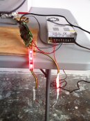
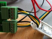
I'm attaching some pictures so you guys don't think I'm crazy. First picture shows the P2 working with 2 different types of pixels (so I know the wires aren't reversed). 2nd picture shows working pixels hooked up. V+, CLK, DAT, GND.

The P12R's I just got are V+, DAT, CLK, GND.

Again if this is by design I suppose I have to deal with it. It just means I need to make some cables that reverse Clock and Data when connecting to P2. It would have been nice if all of the J1SYS gear used the same order.
 

Attachments

  • IMG_1148.jpg
    IMG_1148.jpg
    2 MB · Views: 37
  • IMG_1149.JPG
    IMG_1149.JPG
    1.9 MB · Views: 36
Bill, the P2 and P12R have the same connectors and layout
from left to right of 1 it is G, Clk, Dta, V+

The 2 pin power from the left is -V +V (K1 marking is -V)
 
oops on not putting labels on the silkscreen of the P2. it's a forest and trees issue. the standard pinout is so ingrained in most previous users that we didn't notice not labeling the board. the PIXAD8 does not have labels either but the P12R got them especially because of the 180 degree rotation of half of the connectors.


ALL pixel oriented outputs are the same:


Left -> Right looking into the socket, top of socket is the keyway: G, C, D, V


G - 0v, Gnd reference for signals


C - Clock


D - Data


V - +V for pixel power (the use of pixel power as disconnected, an input, or an output can change based on your design and use on most of the P2 products. the odds of it being an input, except for quick bench test, on a pixad8 or P12r is very slim)


on an ECG-P2, ECG-D2 the power supply (K1) Left -> Right is: -, +


- = gnd, 0v, or the negative side of a power supply (not a NEGATIVE voltage). this is not an AC ground or chassis ground etc.


+ = +V or the positive side of a power supply


the power should be a WELL regulated 5VDC or a 7V-36VDC input. the K3 jumpers MUST be set appropriately.

-Ed
 
Back
Top