BillInSoFL
Apprentice elf
Back in February-March I bought a single P12R which has 12 outputs. The outputs are Gnd, Clk, Data, +V and that's the way I've been making wiring everything and making connectors.
I recently received 2 more P12R's and 3 - P2's. I am little disappointed that the string outputs on the P2's don't match the P12R (not to mention they aren't labeled). Based on reading here in the forums P2 outputs are Gnd, Data, Clk, V+, which means I think I'm going to have to create special cables when connecting to the P2 vs. P12R.
Can someone confirm?? Are there plans to address this at some point??? I mean it's fine if you only have P2 or P12R, but when you're using as many controllers as I am you'd like everything to be interchangeable.
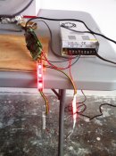
Also due to the somewhat shaky documentation I had some magic blue smoke some out of the OKI-7BSR5. It still seems functional although I'm only testing 12V WS2801 so we'll have to wait and see. I suppose it's good I bought 3, but it's a shame for that to happen because there isn't proper documentation
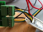
I recently received 2 more P12R's and 3 - P2's. I am little disappointed that the string outputs on the P2's don't match the P12R (not to mention they aren't labeled). Based on reading here in the forums P2 outputs are Gnd, Data, Clk, V+, which means I think I'm going to have to create special cables when connecting to the P2 vs. P12R.
Can someone confirm?? Are there plans to address this at some point??? I mean it's fine if you only have P2 or P12R, but when you're using as many controllers as I am you'd like everything to be interchangeable.
Also due to the somewhat shaky documentation I had some magic blue smoke some out of the OKI-7BSR5. It still seems functional although I'm only testing 12V WS2801 so we'll have to wait and see. I suppose it's good I bought 3, but it's a shame for that to happen because there isn't proper documentation