Navigation
Install the app
How to install the app on iOS
Follow along with the video below to see how to install our site as a web app on your home screen.
Note: This feature may not be available in some browsers.
More options

You are using an out of date browser. It may not display this or other websites correctly.
You should upgrade or use an alternative browser.
You should upgrade or use an alternative browser.
Pixel mounting strips, fuses and distro/fuse boards on sale until end of June 2020
- Thread starter AAH
- Start date
westaussie
New elf
Many Thanks Alan, I received my order today. Very happy with what was in the box. ")
Adsy
Full time elf
Hi Alan my order arrived today. Thanks for the prompt service I'll be back
I have the same HP supplies they are very common from the DL380 / ML380 range of servers.They appear to be the exact same pinout on the connector.
The pinouts are close but not exactly the same. I think they are 1 pin off from your board design for the 12v / Ground
HP - DPS 800 GB
12v pins 1-12, 53-64
Ground pins 13-24, 39-52
pson/pskill 31-24 - you jumper these to power the supply on.
I managed to generate a little magic smoke when testing one a few days ago
Adsy
Full time elf
i can confirm also that these do not work with DPS 800 GB but fortunately no magic smoke. I have ordered the HP DPS 1200 to cover this and will use the hexfuse for the DPS 800I have the same HP supplies they are very common from the DL380 / ML380 range of servers.
The pinouts are close but not exactly the same. I think they are 1 pin off from your board design for the 12v / Ground
HP - DPS 800 GB
12v pins 1-12, 53-64
Ground pins 13-24, 39-52
pson/pskill 31-24 - you jumper these to power the supply on.
I managed to generate a little magic smoke when testing one a few days ago
SMP
New elf
Hi, not sure if anyone can help with this, I purchased a power 8 distribution supply and can’t seem to get the null buffer to work correctly, could be just my lack of knowledge, I have connected to my power supply which works but when I try connecting my data line which is coming from a 5v source thru the null buffer my ws2811 bullet leds go crazy, right now I just have 100 connected but about to connect to another 200 leds. I’m not sure what I’m doing wrong. Thank you for your time.
- Thread starter
- #22
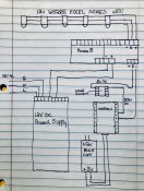
Can you post a picture or 2 of the wiring and/or a scribble to indicate the distances between pixel data source and the Power8 and the Power8 to pixels.Hi, not sure if anyone can help with this, I purchased a power 8 distribution supply and can’t seem to get the null buffer to work correctly, could be just my lack of knowledge, I have connected to my power supply which works but when I try connecting my data line which is coming from a 5v source thru the null buffer my ws2811 bullet leds go crazy, right now I just have 100 connected but about to connect to another 200 leds. I’m not sure what I’m doing wrong. Thank you for your time.
SMP
New elf
Everything is within 12in or shorter connected, I was thinking I may have not connected it correctly. I hope you can understand my picture, this is how I connected the first time and the pixels did come on and would react to my program changes but not the right way, very erratic. So then I changed the wiring, removed the data line from the buffer and connected it direct and everything worked as it should. Of course this was just the first 100 pixels out of 300, and I was anticipating data corruption once I connect all 300 and was hoping your pixel buffer would fix that. Each set of 50 pixels is approximately 17ft with power injection every 2 sets. This is my first try with this, I am a recently retired soldier, not a electrical engineer by any means, so I am learning as I go. I appreciate any help you are able to give. Thank youCan you post a picture or 2 of the wiring and/or a scribble to indicate the distances between pixel data source and the Power8 and the Power8 to pixels.
Attachments
- Thread starter
- #24
Your drawing does make sense and I hope that there's a wire that you left off. You don't show a -ve power connection to the level converter. You shouldn't need that anyway as the null will convert from 3.3V logic to 5V as part of it's function.Everything is within 12in or shorter connected, I was thinking I may have not connected it correctly. I hope you can understand my picture, this is how I connected the first time and the pixels did come on and would react to my program changes but not the right way, very erratic. So then I changed the wiring, removed the data line from the buffer and connected it direct and everything worked as it should. Of course this was just the first 100 pixels out of 300, and I was anticipating data corruption once I connect all 300 and was hoping your pixel buffer would fix that. Each set of 50 pixels is approximately 17ft with power injection every 2 sets. This is my first try with this, I am a recently retired soldier, not a electrical engineer by any means, so I am learning as I go. I appreciate any help you are able to give. Thank you
Having a null at the start of the wiring won't affect anything downstream of the first pixel unless the first pixel itself is getting dodgy data. Every pixel regenerates the signal and the signal will always be clean from pixel to pixel unless there is too great a distance between 2 pixels or the voltage at the pixels to too low to run the internal electronics of the pixel reliably.
SMP
New elf
Sorry, I didn’t show the 5 or the 3.3 reference voltage going to the level converter, I thought the drawing would be to messy, but what you said makes sense, if the buffer also converts 3.3 to 5v then that would explain why my lights went crazy, from that I guess what your saying, I don’t need to use the line converter if going thru the buffer. I went by the normal setup not using a power distribution board by converting the 3.3 coming out the nodemcu into the 5v the lights need. Tonight I was able to connect 3 sets bypassing the buffer and didn’t have any issues, my concern is when I connect the next three sets (with power injection) because of the distance to the last pixel. I was thinking of use a f-amp to combat that problem, unless I don’t experience any issues.