Power Injection/Wire Load/Fuses

layzer1

New elf
Joined
Jan 2, 2020
Messages
43
Hello,

I am trying to understand best practices for power injection and how much load can be put on a cable before frying it. I have an F16v3 with 2 power supplies (PS1/PS2), to power each side of the board and using 12v pixels.

I have a strand of 400 lights I want to connect to port 1 and each port can only support 5amps before blowing out. This puts me at around 6.6amps on port 1 based on .055w/pixel and @30% brightness which puts me over the 5amp fuse. I have attached a drawing help illustrate my question.

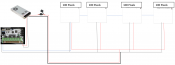
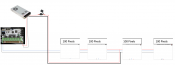
In scenario 1, i connect 4 strands (100pixel/strand) and cut off power at pixel 200 and connect pixel 201 using the same power supply (1) with a fused wire to avoid blowing out the 5amp fuse on the F16v3 port 1.

In scenario 2, I connect 4 strands (100pixel/stand) and power inject between pixel 200 and 201 using the same power supply (1). My question in the scenario is, since the F16v3 can only handle 5amps out of port 1, if I power inject between pixel 200 and 201 using same PS1, will this be an issue with the amp on port1? Will using the method be an issue with too much amp load on the 18awg wire from all 4 strands connected to each other? What is the max amp load on 18awg when connecting multiple strands of lights?
 

Attachments

  • Power Injection Diagram.docx
    240.6 KB · Views: 69

Old Salt

Apprentice elf
Joined
Dec 8, 2020
Messages
80
Use a separate fuse block.
If using multiple power supplies, connect the negative leads together.
Do NOT connect the positive leads together at any point in your circuit.
Feed each power supply to a separate fuse block, and distribute as needed from there.
Connect your controller to ONE of the fuse blocks for power.
Feed the data outputs and ground from your controller to the strings as needed. Do NOT use the fuses on the controller.

Fuse blocks are readily available from auto parts stores, and on-line retailers.
 

TerryK

Retired Elf
Joined
Feb 9, 2020
Messages
655
Location
West Central Ohio
18 AWG single conductor in free air is approximately 7/8 amps. For 3 conductors in a cable, it needs de-rated a bit down to about 5/6 amps. The actual values depend somewhat on the insulation type and ambient temperature (and a few other things). I do not have an absolute value but anything much over 7/8 amps will start to cause wire heating. I fuse 18 AWG at 5 Amp but realize that a 5 Amp fuse will pass 6 or more amps for quite a long time before it finally blows.

Either design will be all right I think. I do highly suggest that from the supply to the strings that you also run the v- along with the v+. Without the v- all of the strings 'ground' current is forced back through the controller. My understanding is the controller v+ is fused, the controller v- is not which may result in traces burning on the controller PC board.
Of the 2 versions, I would go with the first because it has a more even power division in the strings. Although if I may offer a 3rd design, bit more complex, similar to the 2nd design but add another power injection at the end of the 4th string.
 

i13

Dedicated elf
Joined
Jul 5, 2013
Messages
1,172
From a power perspective, this is how I'd wire it. I'm not sure how many pixels you'll get in a line before power injection is needed but I'd do it this way if 200 works. Given that it is 12V running at 30% brightness, I wouldn't be surprised if you can get 200. I realise that there is a negative loop in this diagram and there's a small chance that it could cause flickering. If the pixels work but with an occasional flicker, try disconnecting the negative from the Falcon to the first pixel in my diagram.

What I don't understand (and I've not edited it in the diagram) is how you're trying to run the data. You show it branching like power. Pixel data needs a linear flow from one set of pixels to the next.

There are limits to the amount of current that a wire can carry. In reality, unless there's a short thin section in the wire, you're likely to get voltage drop causing incorrect colours on the pixels before you reach the threshold at which the wires heat up too much.

When using brightness (and therefore data) to limit the current draw, keep in mind that if the data goes corrupt, the pixels may flicker and exceed the brightness that you're designing for.
 

Attachments

  • Power Distribution 1.png
    Power Distribution 1.png
    144.8 KB · Views: 63
Last edited:

layzer1

New elf
Joined
Jan 2, 2020
Messages
43
From a power perspective, this is how I'd wire it. I'm not sure how many pixels you'll get in a line before power injection is needed but I'd do it this way if 200 works. Given that it is 12V running at 30% brightness, I wouldn't be surprised if you can get 200. I realise that there is a negative loop in this diagram and there's a small chance that it could cause flickering. If the pixels work but with an occasional flicker, try disconnecting the negative from the Falcon to the first pixel in my diagram.

What I don't understand (and I've not edited it in the diagram) is how you're trying to run the data. You show it branching like power. Pixel data needs a linear flow from one set of pixels to the next.

There are limits to the amount of current that a wire can carry. In reality, unless there's a short thin section in the wire, you're likely to get voltage drop causing incorrect colours on the pixels before you reach the threshold at which the wires heat up too much.

When using brightness (and therefore data) to limit the current draw, keep in mind that if the data goes corrupt, the pixels may flicker and exceed the brightness that you're designing for.
Thank you for the response. In my diagram, the red V+, black V-, blue is data. The V+,V-, data are coming from port 1. What I'm trying to get my head around is not blowing out the 5amp fuse on port 1. So if i inject power between pixel 200 & 201, will power travel back to port 1 5amp and pop it or will the 5amp power Injection coming straight from power supply meet the need? Sorry if this doesn't makes sense, I'm no electrical guru and proud that I was brave enough to wire my power supply
 

i13

Dedicated elf
Joined
Jul 5, 2013
Messages
1,172
It might or might not blow the fuse. Assuming that this is a continuous line of pixels, your furthest pixels from the injection point (pixel 1 and pixel 400) are the same distance from it. Data is directional but power isn't so you can connect data (without power) at pixel 1 and power will travel backwards to it from the injection point next to pixel 200. In my diagram, all pixels are powered through the injection point and it isn't possible to blow the fuse on the Falcon.

I still think the data isn't quite right in your diagram. I've attached another diagram showing how I think the data should be. I've not changed anything in the power compared to my last version of your diagram.
 

Attachments

  • Power Distribution 2.png
    Power Distribution 2.png
    123.8 KB · Views: 37

TerryK

Retired Elf
Joined
Feb 9, 2020
Messages
655
Location
West Central Ohio
Ignoring the data line wiring, depending upon how hard you are driving the pixels:

In your scenario 1, the controller fuse will protect strings 1 and 2. The power supply fuse will protect strings 3 and 4.

Scenario 2 creates a cascade fuse failure situation whereas when a fuse fails (either one) the other gains the full load and then fails too.
 

i13

Dedicated elf
Joined
Jul 5, 2013
Messages
1,172
I just realised that I slightly messed up the first paragraph in each of my above posts. I should have said 100 instead of 200 in my fist post. This is not a continuous line of pixels from a power perspective; it is four lines of 100. You shouldn't have a problem with voltage drop causing incorrect colours but if you do, I'd still expect it to happen before wires heat up too much.
 

layzer1

New elf
Joined
Jan 2, 2020
Messages
43
I just realised that I slightly messed up the first paragraph in each of my above posts. I should have said 100 instead of 200 in my fist post. This is not a continuous line of pixels from a power perspective; it is four lines of 100. You shouldn't have a problem with voltage drop causing incorrect colours but if you do, I'd still expect it to happen before wires heat up too much.
My apologies, my diagram wasn't clear. These are supposed to be 4 strands of lights all connect together 1=>2=>3=>4.
 

TerryK

Retired Elf
Joined
Feb 9, 2020
Messages
655
Location
West Central Ohio
...
You shouldn't have a problem with voltage drop causing incorrect colours but if you do, I'd still expect it to happen before wires heat up too much.
...

Not entirely but I somewhat disagree. Perhaps not necessarily incorrect colors but erratic pixel operation. Ignoring ambient heating, wire heating is typically from amperage exceeding a conductor's amperage rating. Voltage drop is a combination of wire length and amperage. Voltage drop would of course increase with wire heating as heating increases a conductor's resistivity per unit distance.
A situation of high load and short conductor lengths could I think exhibit wire heating and low or minimal voltage drops. A MEGA tree perhaps; a lot of lights in a relatively small area. Any way one sees it, I feel wire heating and voltage drop outside of a design's normal operation would be caused by not well considering a configuration/design and/or cutting corners in the design to possibly minimize costs.
 

layzer1

New elf
Joined
Jan 2, 2020
Messages
43
Not entirely but I somewhat disagree. Perhaps not necessarily incorrect colors but erratic pixel operation. Ignoring ambient heating, wire heating is typically from amperage exceeding a conductor's amperage rating. Voltage drop is a combination of wire length and amperage. Voltage drop would of course increase with wire heating as heating increases a conductor's resistivity per unit distance.
A situation of high load and short conductor lengths could I think exhibit wire heating and low or minimal voltage drops. A MEGA tree perhaps; a lot of lights in a relatively small area. Any way one sees it, I feel wire heating and voltage drop outside of a design's normal operation would be caused by not well considering a configuration/design and/or cutting corners in the design to possibly minimize costs.
So I'll stick to power injection as to not exceed 5amps of lights which is around 300 12v pixels @30% brightness and not to exceed 7amps on any given wire run and not to exceed 80% of amps/per power supply(LRS350w 30amp). I'll get a power distribution board to inject where needed. Does this sound about right?
 

i13

Dedicated elf
Joined
Jul 5, 2013
Messages
1,172
If it is a continuous run of lights then I'd suggest trying this. The negative loop is still there but disconnecting the negative between the controller and first pixel would get rid of it. Doing it this way removes the 5A limitation because you're not powering through the controller.
 

Attachments

  • Power Distribution 3.png
    Power Distribution 3.png
    134 KB · Views: 37

TerryK

Retired Elf
Joined
Feb 9, 2020
Messages
655
Location
West Central Ohio
So I'll stick to power injection as to not exceed 5amps of lights which is around 300 12v pixels @30% brightness and not to exceed 7amps on any given wire run and not to exceed 80% of amps/per power supply(LRS350w 30amp). I'll get a power distribution board to inject where needed. Does this sound about right?
Should all be all right. I do not really see a need for a power distribution unit but that is a subjective decision, so OK. At the 30% you mentioned the power supply is quite oversized but that too is all right. Essentially, the number of pixels and drive levels result in a light-weight display so power injection and component sizing is rather forgiving.
 

TerryK

Retired Elf
Joined
Feb 9, 2020
Messages
655
Location
West Central Ohio
If it is a continuous run of lights then I'd suggest trying this. The negative loop is still there but disconnecting the negative between the controller and first pixel would get rid of it. Doing it this way removes the 5A limitation because you're not powering through the controller.
A Data Line only between a controller and first pixel is not something I would suggest due to voltage rise in the common carrier (V- or Ground conductor) which may result in erratic pixel operation. Granted, this depends upon pixel currents, voltage drops, and conductor lengths as such. While on a test bench I have run data line only to pixels, it is not something I would do in an active display. Elimination of a controller/pixel/supply ground loop is not exactly easy and would require separate controller and pixel supplies with isolated V negatives. Optical isolation on pixel outputs would be another possibility but I do not know of any controllers with that capability.
 

layzer1

New elf
Joined
Jan 2, 2020
Messages
43
Should all be all right. I do not really see a need for a power distribution unit but that is a subjective decision, so OK. At the 30% you mentioned the power supply is quite oversized but that too is all right. Essentially, the number of pixels and drive levels result in a light-weight display so power injection and component sizing is rather forgiving.
Based on 400 pixels x .055 watt(per pixel) x .30 brightness puts me at 6.6amps which puts me over the 5amp on controller port 1 which is why I was trying to power inject at pixel 201and cut power at pixel 200. I provide an updated diagram, not sure if that helps.
 

Attachments

  • Power Injection Diagram.docx
    254.4 KB · Views: 23
Top