Power Injection/Wire Load/Fuses

i13

Dedicated elf
Joined
Jul 5, 2013
Messages
1,172
I think the 0.055 figure should be the current in amps, not the power in watts. That said, you still arrived at the correct figure of 6.6 amps. This is a worst-case-scenario figure. With most pixels drawing less than that, the whole lot might be under 5 amps at 30% brightness. I still prefer not to power through the controller, let alone 400 pixels but this is just a personal preference. There are a couple of reasons:
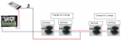
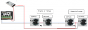
  1. If the data messes up and (worst case scenario) turns on the pixels at 100% brightness white in your scenario 1, this would add up to 0.055 amps × 200 pixels = 11 amps through the controller. The fuse should blow without the controller getting damaged. In your scenario 2, the current in each path will depend on the resistance of each path.
  2. The ends of a long run of pixels aren't usually a convenient place to connect power. When you inject power part-way along the string, you can power in both directions and therefore power twice as many pixels with the one injection point if your power injection cable is thick enough. Both diagrams attached to this post show powering in both directions.
Asssuming that it passes bench testing with voltage drop, I would power it as in the attached Power Distribution 4 image. If I wanted to keep the fuses below 5 amps, I'd do it as in the attached Power Distribution 5 image.

We're getting to the point where any of the proposed layouts (yours and mine) are likely to work. It is just a matter of figuring out which is the most sensible and practical. For example, if your power supply is positioned close to the controller then your layouts might be easier to build than mine.
 

Attachments

  • Power Distribution 4.png
    Power Distribution 4.png
    221.7 KB · Views: 22
  • Power Distribution 4.png
    Power Distribution 4.png
    221.7 KB · Views: 23
  • Power Distribution 5.png
    Power Distribution 5.png
    183.9 KB · Views: 24

TerryK

Retired Elf
Joined
Feb 9, 2020
Messages
655
Location
West Central Ohio
Based on 400 pixels x .055 watt(per pixel) x .30 brightness puts me at 6.6amps which puts me over the 5amp on controller port 1 which is why I was trying to power inject at pixel 201and cut power at pixel 200. I provide an updated diagram, not sure if that helps.

First, might I ask you to consider another attachment format than the docx? My computer complains every time I online open them. :)

The injection at the 200/201 pixels and 6.6 Amp, yes, I noticed. I still prefer the 1st, a more even power distribution across the strings. The fuse at the supply, probably another 5 Amp just like the 5 Amp fuse on the controller.

I haven't commented yet on voltage drop as I do not think cable lengths have yet been mentioned. Perhaps I should have. As i13 indicated, because the design is being configured at a 30% drive, problems will occur if drive levels go higher so limitations will need implemented, somewhere. If you would indicate cable lengths voltage drops could be looked at.

i13's PD#5 is similar to what I do but without knowing a bit more about it I see a possible problem regarding supply size and cable AWGs.
 

layzer1

New elf
Joined
Jan 2, 2020
Messages
43
My longest cable run is approximately 15ft from controller and bought a few f-amps. I was thinking of 18/4 cable and doubling up two wires(approx 15awg based on online calculator) for power injection and also using the same wire for normal wiring (2 wires) V+, (1wire) V-, (1wire) data. I have 2 mean well 350w 29amps power supplies.
 

TerryK

Retired Elf
Joined
Feb 9, 2020
Messages
655
Location
West Central Ohio
If the longest is 15 feet I doubt you will need a F-Amp. I would omit it and only install one if you see problems. If you are still looking at a 6.6 amp display, only a single 350 Watt supply is needed.

For the cable runs, supply through fuse to string and supply to controller, the 2 wires for V+ and 2 for V- are all right. I would suggest for the controller to the string to use 1 wire for V+, 1 for data,, and 2 for V-. Your display is light enough I do not feel it really matters but given an option it is usually better to help maintain the Data Line to circuit common (Ground/V-) reference.
 
Top