Navigation
Install the app
How to install the app on iOS
Follow along with the video below to see how to install our site as a web app on your home screen.
Note: This feature may not be available in some browsers.
More options

You are using an out of date browser. It may not display this or other websites correctly.
You should upgrade or use an alternative browser.
You should upgrade or use an alternative browser.
Rainbow Wall Wash - Current issue
- Thread starter cenote
- Start date
budude
Way behind schedule - again...
You may want to jump on the christmasonmanor.com forum and post your results to Greg to see what's up. If things are this far off I'll be disappointed as I got these because they seemed like a better solution than the MightyMini's (and were cheap too). I can't afford RJ's Aethers (at least not 4-6 of them) so I'm hoping this can be resolved. :'(
ponddude
Apprentice elf
I was made aware of this post today, so I am sorry for not jumping in here sooner.
First off, I would like to know how you are testing these. I just tested the LEDs seperately and they are drawing between 29 and 30 mA a piece. I than went and tested a flood, which is drawing 538 mA for the entire red channel, which is well within the estimate for what it should be drawing. (540 is exactly 30*18) I don't doubt that you are testing the lights correctly, but I can't see that big of a difference between the lights.
Just to let everyone know, the lights are designed for LEDs that are spec'd as the following:
RED 30ma 3 LEDs @ 2.4Vf
GREEN 30ma 3 LEDs @ 3.6Vf
BLUE 30ma 3 LEDs @ 3.6Vf
To add to it, the LEDs will run perfectly fine if you are running them at 33mA. The chip inside these LEDs is rather large and can take a beating. I wouldn't even doubt that running these at 40mA wouldn't harm them. Furthermore, I have 2 of these installed in the back of my house lighting up my backyard. They have been out there since around the beginning of March and I don't have a single LED out. Nothing has changed in the LEDs we are using or their specs.
If anyone ever has a questions about our stuff, either post over on my forums at www.christmasonmanor.com/forums or send me an email directly at greg@christmasonmanor.com. I stand behind my stuff and would not release something with this big of a difference in LEDs and resistor values.
Greg
cenote
Suburbs of Philadelphia
- Thread starter
- #19
ponddude said:First off, I would like to know how you are testing these. I just tested the LEDs seperately and they are drawing between 29 and 30 mA a piece. I than went and tested a flood, which is drawing 538 mA for the entire red channel, which is well within the estimate for what it should be drawing. (540 is exactly 30*18) I don't doubt that you are testing the lights correctly, but I can't see that big of a difference between the lights.
Greg
NO big deal yet.....I've told everybody I've been talking with, I very well could be wrong. I built both a wall runner and a flood, but I did not solder the resistor in to bus side, only soldered it to the side feeding the LED's. I than tested using a 200mA setting on a the meter, and came up with suspiciously high mA readings. The red's are the only ones that seemed to be way out in front of the 30ma ratings. I was getting between 45 and 60 mA on Reds as they heated. I am planing in using them year around like yourself to burn in my landscaping, so I have decided to make sure that the LED's are burning at there most stable current, which from everything I can find, yes they will handle 30mA, but reading specs all over the web, these seem to last the longest at about 25ma.
Have to agree, there is NO visible difference in the lights between 25 and 30ish mA. But When I first assembled the wall runners, and each series of led's were pulling high, they looked horrible to me. Some were only burning what seemed to be 1/2 brightness, and other seemed to be able to literaly blind you. This is what made me investigate the current draws. After hooking up 25mA cc's on the runners, all problems went away with the different shades of reds.
It was never my intent to slander you or any of your products. And if I have, please let me apologize. You can ask anybody that that I have talk to in the last week, I have repeatably said that there could be errors in my ways, and I did not have any intent to contact you, till I was 100% sure of findings. I have told everybody since the NJ mini, to go out and buy your products, and that you will not find a better value.
budude
Way behind schedule - again...
Hi Greg -
I'll move any more discussion of what I'm seeing over to your site - but wanted to close here on how I tested this.
I have a single RF connected to my Ren48LSD running at 12v. I verified I have exactly 12.0v at the input to the RF (I use an adjustable lab suppy). I measured the 180ohm resistors at ~177ohms each. I had a constant on Vixen sequence running and measured the voltage across each resistor. I then calculated the current for each resistor and it averaged about 33mA per resistor (with a +/- 2mA range). I plan to repeat this for the Blue and Green LED paths as well. Obviously if these were 20mA LEDs as I originally thought I got worried but I agree that 33mA might be OK or I could always drop the voltage a bit to get them under 30mA if necessary.
Anyway - thanks for the reply and I'll move this your site from here on out.
ponddude
Apprentice elf
Chuck,
In absolutely no way do I think you were "slandering" my stuff. I hope I didn't come across that way as i was just trying to explain how things were designed to run. Questions are what make the world go round, so I always welcome them. I hate the fact that emotion doesn't translate through the internet.
I really am just questioning why you are seeing differences in the LEDs themselves. There always is the chance that that there is a grouping of bad LEDs in your mix. There also could be an issue with one of your resistors. The explanations really are endless as to why you are seeing this but when push comes to shove, you shouldn't be seeing the issues. Is this happening on all the things you bought or just one of the lights?
Greg
cenote
Suburbs of Philadelphia
- Thread starter
- #22
ponddude said:Is this happening on all the things you bought or just one of the lights?
Greg
I have only played with 1 flood and 1 runner. The flood light was @ 38-45mA on reds, and the runner was pushing 55-60mA with 11.8v Since, I have upgrade my transformer to a solid 12.0v tested at the flood, and was getting in the 40's with the red's. Going to assemble another runner hopefully tonight.
I'll drop you an email later after I retest a new light.
Chuck
My only thought is are the LEDs being damaged by excessive heat during soldering? This can result in dim / defective LEDs.
JerryPlak
New elf
Chuck,
Let all of know more about the CC you are using 8)
Let all of know more about the CC you are using 8)
ponddude said:Just to let everyone know, the lights are designed for LEDs that are spec'd as the following:
RED 30ma 3 LEDs @ 2.4Vf
GREEN 30ma 3 LEDs @ 3.6Vf
BLUE 30ma 3 LEDs @ 3.6Vf
I'm not debating if the leds can handle certain currents, i overdrive leds all the time for my own use with knowledge of the increased risk of failure.
What i am going to take up is the whole Forward Voltage issue and just selecting resistors without measuring each set.
Even though Pondude states above the Specs for Leds, the supplied Resistors indicate the Vf used to calculate them was
Red - 2.2v
Grn - 3.5v
Blue - 3.5v
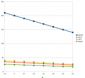
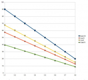
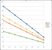
Now the graphs below show what happens with different forward voltages.
Expect R is the the resistor value that should be used for each Vf
I sup R is the Current that will be drawn for each Vf using the supplied resistor
I cal R - as above if you used the calculated resistor for 30mA at 3.6 from specs
I Used R - as above for the resistor that cenote used and measured
The closer the total Forward voltage drop of the LED's to the supply current the more critical it is to take into account variations in VF when using resistors.
To make a statement that the Vf should be the same because they are from the same batch whilst always stated is not really that valid.
I have seen surface mount leds from the same reel have up to 10% variation in the current with the same resistor values.
I keep saying this and will continue to say it AND even more so when dealing with parallel strings
YOU MUST MEASURE Vf.
I'm happy to supply the original spreadsheet if the figures are in doubt.
Cheers
Phil
Attachments
I have 4 of the rainbow wall washers (RWR) and after reading and seeing the suspect design of 5 red LEDs in series with a 2 ohm resistor, i thought i better gives these a run.
I tested these connected to multi strand CAT 5 cable with a length under 2 feet to minimize voltage drop with a stable 12VDC power supply connected through an amp meter.
I ran the RWR at precisely 12vdc for a 2 hour period while checking the red input current. The current went up to 0.35 amps for 10 red LEDS and the LEDS didn't exhibit any excessive heat, The CAT 5 cable also showed no signs of heat.
It appears that the RWR will survive as long as you maintain 12vdc or less, anything over this may burn them out as the LEDS are configured as 2 x 5 series red LEDS. Its not a good practice to be using 5 LEDS in series with a 2 ohm resistor as the current going through these LEDS would be 350ma / 2 = 170ma per series circuit.
On saying that it appears to work without any issues, heat build up or the LEDS self destructing as the piranha LEDS are very tough and are usually used in the automotive industry. The issue that may arise for us down under is that during our summers our ambient temperatures are a lot warmer and i could see this drawing 400ma on the red.
The rainbow floods don't have this issue as they configured into 6 x 3 LED circuits which is a better design.
budude
Way behind schedule - again...
I guess I need to change my userid to "Doubting Thomas"... ")
I'm guessing that the same Piranha LEDs are used for the RFs as the RWRs and they are rated at 30mA so I find this hard to believe they are running at 170mA? It almost sounds you are an entire magnitude off (i.e. digit needs to move over one to .035A or 35mA/2) and perhaps they are 20mA LEDs so they are getting 17mA each which would be reasonable. Greg mentioned using 20mA LEDs at one point and 30mA later on but not sure if it applies to these...
I'm guessing that the same Piranha LEDs are used for the RFs as the RWRs and they are rated at 30mA so I find this hard to believe they are running at 170mA? It almost sounds you are an entire magnitude off (i.e. digit needs to move over one to .035A or 35mA/2) and perhaps they are 20mA LEDs so they are getting 17mA each which would be reasonable. Greg mentioned using 20mA LEDs at one point and 30mA later on but not sure if it applies to these...
These are the same LEDS used in the rainbow floods, my meter showed 0.35 Amps for the red but i will double check this tonight and confirm. Either way they seem to work well and I'm not too fussed as there was no real heat build up on the LEDs themselves. But there was a bit of heat coming from the pins of the LEDs and the tracks but not enough to not be able to hold for long periods.
ron
Apprentice elf
Brian,
I think Eddy is talking about 170mA across a 5 LED series circuit, which would be 34mA per LED. More in line with your thinking?
Still maybe a little high, but close to the 30mA rating for the LEDs (assuming they are 30mA and not 20mA rated).
Ron
I think Eddy is talking about 170mA across a 5 LED series circuit, which would be 34mA per LED. More in line with your thinking?
Still maybe a little high, but close to the 30mA rating for the LEDs (assuming they are 30mA and not 20mA rated).
Ron
budude
Way behind schedule - again...
ron said:Brian,
I think Eddy is talking about 170mA across a 5 LED series circuit, which would be 34mA per LED. More in line with your thinking?
Still maybe a little high, but close to the 30mA rating for the LEDs (assuming they are 30mA and not 20mA rated).
Ron
No - since the LEDs are in series, each LED is at the same current. If they were all parallel then this would be a possiblity but then there would be a resistor for each LED which is not the case. Sorry - I still think there is an extra '0' missing here...