What's wanted

I don't know if people would want the extra wiring and expense? Getting all pixel board manufacturers to implement it could also be tricky.

The daisy chaining is also a not an insignificant issue. What happens with custom made props? They would need an extra module programmed to suit and that would have to be done by the end user.

The overall idea is nice in general, but i don't see it as being viable. Happy to be proven wrong of course.
 
Getting all pixel board manufacturers to implement it could also be tricky.

I think it'd have to be part of the E1.31 standard / protocol even before pixel board manufacturers took it onboard, and would probably have to start at the pixel IC level even before then.

What happens with custom made props? They would need an extra module programmed to suit and that would have to be done by the end user.

Yep, but possibly no more difficuilt then currently building a prop + wiring for power + controller configuration + sequencing software configuration.

I'm not sure whether it should be done at the Pixel level or by simply inserting an in-line chip/IC between pixels and controllers
 
IMHO about the only way that something like this could be implemented would be some sort of standalone pixel controller that includes current measurement and some sort of motion capture interface kinda like I believe xlights is capable of already. Each pixel would have to be turned on in turn, mapped and the current measured. Theoretically the current is going to be something like 55mA per pixel as per design specs but it can be varied. Once the model is mapped in then you would need to process sub models etc. For flat 2d models it is quite an easy process but for 3d models like a mega tree it would be kinda next to impossible as what they look like in a 2D render wouldn't translate well to something easily understood.
Pixels themselves are incredibly dumb devices. They simply look for a reset signal, grab the next 24 bits of data and then pulsewidth modulate the R,G,B channels based on that info. They have no way of providing feedback and they are unaware of whether there are any pixels before or after them.
As an alternate option something like an RFID tag with embedded info could be used for pre-built props. Boscoyo and a few other suppliers are already supplying wiring and model info for xlights but it's not really economically viable to supply pre-built props with pixels as they then get heaps heavier and bulkier and more expensive to transport.
 
Hi, this could be done but it would come with a cost and initially not a small cost when you consider that all the manufactures would need to recoup their time developing this. I suspect if it was ever trialled the down fall would be that other members would correctly suggest that they could map and supply you with the same information at a significantly reduced cost. A good idea for selling to none-DIY members but I’m not sure there is much mileage here.
 
I think I may of got ahead of myself on this and want too much!

As I said in my first post, telemetry reporting / monitoring of the pixel or pixel string to me is whats wanted, which obviously requires alot of work in the pixel IC itself and basically rebuilding them to be 2-way communication capable, which in turn would need to be adapted into the controllers later on, whether this could be absorbed into E1.31 protocol or a whole different "PDP" (pixel discovery protocol) written I dont know (I'm not that smart).

I think if the above could be achieved you'd have a bit more of a platform to build upon and do some pretty nifty things, and also really make troubleshooting so much easier if pixels were able to report things like voltage, current and capability back to the controller.
 
Just giving this thread a bump to see if anyone has anything on their wish list for hardware (not software) devices.
On my wish is a basic relay (multi channel) controller that can be driven as a pixel channels. I have experimented with the dimmers to do this with mixed results.
 
On my wish is a basic relay (multi channel) controller that can be driven as a pixel channels. I have experimented with the dimmers to do this with mixed results.
@Roosta created something similar to this several years ago and it was a beast. I hope he has photos of it he could share. I converted him from his beast to using 1 of my 2811DC15's which can drive relays or solenoids with just the need to add a protection diode per relay or solenoid.
 
Hmm, I bought a bunch of those boards with the hope I could use with relays but the relays I hooked up didn't seem happy. Would activate sometimes and made a funny noise. What type of diode do I need?
 
Hmm, I bought a bunch of those boards with the hope I could use with relays but the relays I hooked up didn't seem happy. Would activate sometimes and made a funny noise. What type of diode do I need?
A 1n4004 diode like on https://auschristmaslighting.com/wiki/File:Relay_Mod_Schematic-png
The channels need to be fully on or fully off with no attempt at dimming. This also means no dimmed through reducing overall brightness settings in sequencer and/or pixel controller.
 
Thanks heaps... I will give that a go. What's the logic of this, I was of the thinking that a full bright output would have just been enough to close the relay.
 
A coil on a transformer, relay or solenoid is exactly the same as on a car ignition coil. When power is applied the magnetism builds and when the power is removed the magnetic field collapses and a voltage (back EMF) is produced. By turning a relay on and off the only time the back EMF is produced is at the time the relay gets turned off. The voltage produced can be quite high which can damage the transistor/mosfet driving the coil. When the channel is dimmed it is actually being turned on and off hundreds of times a second so the relay itself won't be overlay happy at the attempts to pull in and release hundreds of times a second but also every time the coil/channel is turned off the back EMF is produced. On or OFF for a coil. Never dimming.
 
That's why on my DMX relay boards i have logic in there to stop the relays from being rapidly turned on and off. A pixel input relay board could be made, but I don't know how much demand there would be for it?
 
A coil on a transformer, relay or solenoid is exactly the same as on a car ignition coil. When power is applied the magnetism builds and when the power is removed the magnetic field collapses and a voltage (back EMF) is produced. By turning a relay on and off the only time the back EMF is produced is at the time the relay gets turned off. The voltage produced can be quite high which can damage the transistor/mosfet driving the coil. When the channel is dimmed it is actually being turned on and off hundreds of times a second so the relay itself won't be overlay happy at the attempts to pull in and release hundreds of times a second but also every time the coil/channel is turned off the back EMF is produced. On or OFF for a coil. Never dimming.
Thanks for that explanation... I figured I was missing something
 
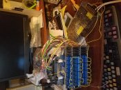
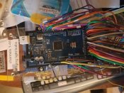
I don't know if this will help you, but I am running my light show with an Arduino Mega and banks of relays each ran by an a Mega controlling 48 relays in this case I am using mechanical relays its what I had. They are programed to work with the vixen software daisy chained together. some running AC and some running DC circuits.
20181104_074819.jpg
20181104_074836.jpg
 
Back
Top