Answered Which cable is which

DougieB

Full time elf
Joined
Aug 3, 2011
Messages
278
Location
Gladstone, Qld
So after 12 days since it cleared customs, my order from Ray Wu finally arrived on Thursday. Thank you Aus Post. In this order is a bunch of 2 and 4 string waterproof connectors and my initial scattering of 2801 pixel strings
2ea of
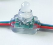
RGB-full-LED-pixel-module-WS-2801-IC-DC5V-input-50pcs-a-string.jpg
12mm-WS2801-pixel-module-IP66-DC5V-input-full-color.summ.jpg
WS2801IC-5050-3LEDS-DC12V-input-waterproof-20pcs-a-string.summ.jpg

awesome, everything as I ordered.
Now my question is in several parts:
On the 12mm round pixels I can make out the +5V, Data, Clock and Ground details, but I can not tell which is the input side. So how do I tell which side is which?

On the square based pixels, I can clearly see the direction of current low, how do I know which cable is which?
The colours are the same for all the strings, so far so good. I can use a multi meter to tell me which is the ground cable, therefore identifying the power in cable, easy.
WHat happens if I feed the power and data the wrong way on the 12mm lights and what damage will I do I confuse the clock and data cable on square based lights?
Is there a simple check I can make to determine correct input/output alignment and which cable is which, or do I need to ask The Man himself?
Please help
Doug
 

DougieB

Full time elf
Joined
Aug 3, 2011
Messages
278
Location
Gladstone, Qld
Thanks David

I had viewed that before posting and just want to check if there is any testing I can do or damage I can cause if I wire incorrectly. My colours are red, yellow, green blue.
Doug
 

David_AVD

Grandpa Elf
Community project designer
Generous elf
Joined
Jun 12, 2010
Messages
4,681
Location
Victoria Point (Brisbane)
By the way, both the power + and - (ground) go right through the string, but there's no sure fire way to tell which is which.
 

DougieB

Full time elf
Joined
Aug 3, 2011
Messages
278
Location
Gladstone, Qld
So if I can positively identify the +5V input, then the ground would be locatable with a multi meter? the data and clock could be located by trial and error

How critical is the feed direction?
One one of the 12mm lights I have been able to identify the green having DO on the non-IC side, could I be safe in assuming that this is Data out?
On the square, I think that I have located the correct order of
Red - Power in
Yellow - Ground
Green - DI (data in??)
Blue - CI (clock in)
The CI and DI is supported by direction markings on the PCB and silicon cover
Does this sound correct
Thanks
Doug
 

David_AVD

Grandpa Elf
Community project designer
Generous elf
Joined
Jun 12, 2010
Messages
4,681
Location
Victoria Point (Brisbane)
So if I can positively identify the +5V input, then the ground would be locatable with a multi meter? the data and clock could be located by trial and error

The +5V and the ground wires are each a continuous circuit from start to end which can be verified with your multimeter reading a couple of Ohms from end to end. You may get a reading on the data and clock wires (from end to end), but it would be a lot higher resistance.

How critical is the feed direction?

It won't work if the direction is wrong, but no damage should occur.

One one of the 12mm lights I have been able to identify the green having DO on the non-IC side, could I be safe in assuming that this is Data out?

Yes, DO is Data Out so that's the output side.

On the square, I think that I have located the correct order of
Red - Power in
Yellow - Ground
Green - DI (data in??)
Blue - CI (clock in)
The CI and DI is supported by direction markings on the PCB and silicon cover
Does this sound correct

The marking on the silicone cover have been known to be wrong too. The PCB should be right. DI is Data In and CI is Clock In.
 

DougieB

Full time elf
Joined
Aug 3, 2011
Messages
278
Location
Gladstone, Qld
Thanks David, feel a lot more comfortable now. Now just need my controllers to turn up and I am good to go.

:D
 
Top