Wiring a Toroid

matt_65

New elf
Joined
Dec 11, 2011
Messages
15
Location
Adelaide
Hi all,


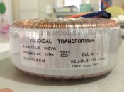
I have recently got me 2 12V-0-12V 300VA toroids and am having some trouble working out how to wire them up.


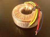
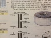
They have 6 cables (orange, yellow, red, black, 2x blue), I want them to be in series so that I can get 24V @ 12.5A.


I have 3-core electrical cable, I guess the red from the electrical cable connects with the red of toroid 1 and the same for the black. I am guessing, given the big difference in cable thickness, that the 2x blue cables are the output.


If I am correct with these assumptions, that would mean that the orange and yellow of toroid 1 would join with the red and black of toroid 2?


Or is what I have described above parallel? Would the red/black from the electrical cable instead join with both red/black cables on both toroids, and something happens with the orange/yellow cables?


In either scenario, which blue cables on which toroid would I use as the output?


I have a 240V 10A fuse that I plan on using inline on the live wire, would only one be sufficient?


I have read that I should also have a fuse on the output, what size fuse should I be looking for? 24V @ 12A?


The toroids are also wrapped in plastic, does the plastic get removed or is it OK to keep it in the plastic?


Thanks for your assistance, my plan is to get it all wired and then try and find an electrician who would be happy to look it over for safety/correctness so I would like to get as much done as possible before I get them out.


Matt
 

David_AVD

Grandpa Elf
Community project designer
Generous elf
Joined
Jun 12, 2010
Messages
4,681
Location
Victoria Point (Brisbane)
Post a picture of the toroid and we should be able to help.

Are the blue wires thinner (less stiff) than the other ones? If so, these will be the primary wires.

Most toroids will have a label on the side (under the clear plastic) that tells you what colours are what.

BTW, the plastic wrapping is part of the construction and stays on. There should also be two large flat rubber washers, a domed steel plate and bolt set for each transformer. It's important to use all of it in the right order / manner.
 

matt_65

New elf
Joined
Dec 11, 2011
Messages
15
Location
Adelaide
The toroid is a MT2130 from Jaycar (http://www.jaycar.com.au/productView.asp?ID=MT2130&keywords=toroidal&form=KEYWORD), image is attached.
[/size]
[/size]Their engineering catalogue has a wiring diagram (attached)


I have the fittings for one, but will need to go back as the other one didn't have them.


Do these things get hot? When I mount them do I need to ensure there is airflow in my box?


Thanks,


Matt
 

Attachments

  • image.jpg
    image.jpg
    1,018.3 KB · Views: 16
  • image.jpg
    image.jpg
    944.7 KB · Views: 14

David_AVD

Grandpa Elf
Community project designer
Generous elf
Joined
Jun 12, 2010
Messages
4,681
Location
Victoria Point (Brisbane)
The blue wires are the 240V primary winding.

There is some detail about the secondaries on the side of the transformer, but it's partly obscured in that photo.

If you post a new photo of that bit we'll have it sorted in a jiffy. :)
 

matt_65

New elf
Joined
Dec 11, 2011
Messages
15
Location
Adelaide
OK, here is the label on the side.


The blue wires are much easier to bend then all of the other wires, they are of a smaller diameter.


Thanks heaps for your time and patience with this.


Matt
 

Attachments

  • image.jpg
    image.jpg
    1 MB · Views: 18

David_AVD

Grandpa Elf
Community project designer
Generous elf
Joined
Jun 12, 2010
Messages
4,681
Location
Victoria Point (Brisbane)
To get the series connection (24V), first join the black and yellow wires together and insulate. Then you can connect the red and orange wires to your 24V AC load.

This should be correct, but check with a meter (on Ohms) first to make sure you get continuity between red and black as well as between yellow and orange. You should get no reading (open circuit) between black and yellow. Do this test before you join any wires.

All being well, you should measure 24V AC between red and orange once you've applied 240V AC to the blue pair of wires. It will actually be somewhat higher (maybe up to 30V) without a load.
 

David_AVD

Grandpa Elf
Community project designer
Generous elf
Joined
Jun 12, 2010
Messages
4,681
Location
Victoria Point (Brisbane)
Oh, yes, you will need a fuse in line with the active on the primary. You could have a fuse on the secondary as well, but the primary fuse is essential.

Here's the mounting detail:

diagram_131.gif
 

matt_65

New elf
Joined
Dec 11, 2011
Messages
15
Location
Adelaide
Great thanks for that David, and thanks for the mounting info, as both rubbers were on the one side I thought that was how it was mounted.


To make sure I understand, I connect the black wire from toroid 1 to the yellow wire of toroid 2, I then connect the live 240V wire to all 4 blue wires? Or did you mean it is black to black and yellow to yellow?


And would it matter which read/orange cable I connect my lights to, or would both pairs be outputting 24V?


And finally, where does the neutral wire from the wall socket connect to?


Sorry for this, I am very much a visual person and am very keen to ensure I get it right.


Thanks again for your time with my questions.


Matt
 

David_AVD

Grandpa Elf
Community project designer
Generous elf
Joined
Jun 12, 2010
Messages
4,681
Location
Victoria Point (Brisbane)
I may have misread your first post. Each toroid is capable of providing 24V AC. Is there a reason you want to connect two transformers together?
 

matt_65

New elf
Joined
Dec 11, 2011
Messages
15
Location
Adelaide
There only 12V, at least that is what I thought. I am under the impression that they are 12V and you can run two of them in parallel to get double the amps (12V @ 25A) or serial to get double the volts (24V @ 12.5A), have I mis-understood this?


Seeing your diagram the wiring makes a heap of sense, neutral to one blue, active to the other, join the black and yellow and the red/orange is output, beautiful.


Would be great if I only need one (just need to try and return the second one then).
 

matt_65

New elf
Joined
Dec 11, 2011
Messages
15
Location
Adelaide
Great, I have just finished wiring up one of the toroids and it powers up nicely and my set of test lights power up too :)


I am not sure of the amps that are being outputed, the lights don't appear very bright and I am not sure if that is how they are.


I can use my multimeter to see that 21V is getting through but for some reason my multimeter is showing 0A.


I will try another set of lights tomorrow night in case it is the lights.


Thanks,


Matt
 

David_AVD

Grandpa Elf
Community project designer
Generous elf
Joined
Jun 12, 2010
Messages
4,681
Location
Victoria Point (Brisbane)
To measure the current, you'll need to use the 10A AC current range on your meter and put the meter inline with one of the transformer output wires.

Don't forget to use the right holes on the meter for current. Post a picture of the meter if in doubt.
 

matt_65

New elf
Joined
Dec 11, 2011
Messages
15
Location
Adelaide
Ah the inline bit was probably where I was going wrong, Ill give it a go tonight.


Matt
 
Top