GS8208 12V pixel strings - A wildcard third option for the 5V vs 12V WS2811 question?

AussiePhil

Dedicated elf
Administrator
Joined
Jun 20, 2009
Messages
1,606
Location
Canberra, ACT, Australia
one of the selling points of these seems to be being able to do longer runs without injection.. anyone tested the limits of that?
after reading all the post and the excellent testing already done I devoured the datasheet as well, missing from most of the diagrams posted is the typical use circuit that includes a resistor from Vdd to R+, would appear to be voltage divider arrangement.
One of Ryans photos above seems to show a 300R resistor but it's hard to read.
The spec sheet gives a Vdd Min of 9v so this imposes a limit for the voltage drop along the string, this is offset by the current draw being less.
Putting some numbers into the Excel sheet for voltage drop calculations says that at 100 pixels we have 10.3v available, so maybe this will stretch the PI point out to 200 pixels.
I'm not prepared to spend the money on strings right now though for testing, seems the availability of bullet or square is limited and may remain that way without demand.

@ryanschristmaslights : any chance you can measure:-
Resistance of a 100 pixel length, no voltage, one end shorted.
The voltage at the start and end of a 100 count string, all white 100%
Please
and get a photo of the resistor?
anything with a faster Serial frequency on the way?
What's it matter?, it's the same as 2811 already based on the datasheet

Cheers
Phil
 

Kent

Apprentice elf
Generous elf
Joined
Nov 21, 2020
Messages
71
I am very keen on these and will get some when available.

I've been communicating with Ray over the last week or so. He has the GS8208 chip and can provide 5V pixels, but for 12V a different LED is used and it is currently unavailable.

My plan was to try again after the lunar new year.
 

MichaelF5

Apprentice elf
Joined
Nov 23, 2016
Messages
76
Location
West Hoxton
I am very keen on these and will get some when available.

Yep, they look top of the heap right now, barring something with a higher data rate coming along

What's it matter?, it's the same as 2811 already based on the datasheet

Cheers
Phil
Some Data says 800Khz, other says higher interestingly...


I've been holding off going near Pixels till something that's "that good" comes along
 

AussiePhil

Dedicated elf
Administrator
Joined
Jun 20, 2009
Messages
1,606
Location
Canberra, ACT, Australia
I am very keen on these and will get some when available.

I've been communicating with Ray over the last week or so. He has the GS8208 chip and can provide 5V pixels, but for 12V a different LED is used and it is currently unavailable.
Using them with 5v parallel led would not work based on the datasheet, they are a 12v solution and a damn good one.
My plan was to try again after the lunar new year.
 

AussiePhil

Dedicated elf
Administrator
Joined
Jun 20, 2009
Messages
1,606
Location
Canberra, ACT, Australia
Yep, they look top of the heap right now, barring something with a higher data rate coming along


Some Data says 800Khz, other says higher interestingly...
From the datasheet
RZ data frequency
Min 400k
Typical 800k
Max 1MHz
This is inline with ws2811

The internal data refresh is set at 100Hz
The (assumed external) data refresh rate is typically 30 with a max of 1017
PWM refresh at 8k

Think I seen a post from AAH quoting 267fps, that goes with the specs above


TerryK

Retired Elf
Joined
Feb 9, 2020
Messages
655
Location
West Central Ohio
Here is a link that provides I think a better comparison of the GS8208 and WS2815

A couple thoughts: I too do not think the GS8208 is intended to or can be designed to correctly operate on 5 Volts. The datasheet indicates it has a built in 7805 so I would not be surprised if it would produce reasonable colors and illumination at operating voltages below the 9 Volts or so indicated as a minimum in its datasheet.
Regarding the resistor and capacitor shown in the datasheet, while a bit vague, the datasheet seems to indicate these are not exactly necessary. With the IC's higher PWM frequency and staggered output switching, I am more inclined to think that the components are a RC network to help prevent the chip's switching transients from radiating back out on the power lines. The WS2815 datasheet indicates a 100nF Bypass capacitor.
 

AussiePhil

Dedicated elf
Administrator
Joined
Jun 20, 2009
Messages
1,606
Location
Canberra, ACT, Australia
Further to the 5V thing..... the GS8206 is 5V capable but runs the LED in parallel the same as most of the chips we know.

GS8208 is 12v only

Erroneous line edited out: the WS2815 DS has the redundant data line labeled BIN and i missed it. I shuuld know that as i ordered 2815 for that reason on Nov :)
 
Last edited:

ryanschristmaslights

Senior elf
Administrator
Joined
Jun 30, 2010
Messages
951
Location
Adelaide, Australia
one of the selling points of these seems to be being able to do longer runs without injection.. anyone tested the limits of that?

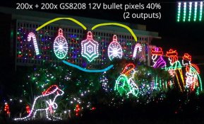
200 pixels at 40% intensity limit with no additional injection (power in at first pixel only) looks good to me. I don't have pixels 1 and 200 next to each other, so I can't say whether you'd notice any difference if they were side-by-side. For my 2021 show 400 pixels were evenly divided across two controller outputs (200 each) at 40% with power at the first pixels only (via fused PixLite outputs). The two round baubles were on one output (blue line below) and the two candy canes + middle bauble on a second (yellow line below).
200x + 200x GS8208 bullet pixels at 40% intensity, evenly divided across two fused controlled outputs

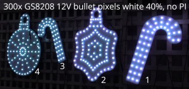
300 pixels at 40% with power supplied only into the first pixel is definitely on the dull side of things. Interestingly this dull white edges towards a greeny-grey rather than pink or yellow:
300x GS8208 bullet pixels at white with 40% intensity, no power injection

Increase to 400 pixels 40% intensity and things go pear shaped with brightness and colour twinkling anomalies from just after the 151st pixel.
400x GS8208 bullet pixels at red with 40% intensity, no power injection, with artefacting problems
Take note of the left candy cane (third prop) with the start of the string at the bottom. Initially the artefacting is only intensity (the red gets randomly brighter, ignoring the 40% intensity limit set in the controller). Then not long past that the artefacting extends into random colours. Looking further along, the last 20-25 pixels in the fifth prop won't light up at all, which is about a quarter of the lights in that prop).

With 400x pixels connected capped at 40%, at the start of the candy cane (pixel 151) the voltage was measured between about 5.8V-6.6V, varying in this range depending on colour. One string further at pixel 201 and it has dropped to 4.8-5.6V. As this is below the 9V min spec seen from a datasheet, I presume then that it is the low voltage causing the random twinkle patterns - in this case starting from about pixel 175. With half of the pixel strings unplugged leaving only 200, then all 200 function correctly at 40%.


But what happens if V+ and gnd are each joined between pixels 1 (first prop) and 351 (last prop) using the included 2-pin PI connectors? Well now things look great at 40% with even whites. At the 151st pixel the voltage now hovers between 8.7-8.8V. That's still not quite 9V but in this instance near enough seems just fine.
400x GS8208 bullet pixels at white with 40% intensity, V+ and ground each joined between pixels 1 and 351

At 100% intensity, 400x pixels won't work correctly even with V+ and gnd joined between 1 and 351. However, 300x pixels with V+ and gnd joined between pixels 51 and 251 (between second and fourth) also seems mostly OK. Occasionally there is intermittent artefacting only on red, but with this not consistently occurring I'm thinking that this might be caused by my very temporary wire joins, not sure. It doesn't occur every time red is cycled, only sometimes and I didn't notice a pattern to it. I haven't tested 1 to 251 as two 2-pin connector pigtails back to back would not reach that far.

I am very keen on these and will get some when available.

I've been communicating with Ray over the last week or so. He has the GS8208 chip and can provide 5V pixels, but for 12V a different LED is used and it is currently unavailable.
A couple thoughts: I too do not think the GS8208 is intended to or can be designed to correctly operate on 5 Volts.

The LEDs in my 12V GS8208 strings start doing some funky things with colours emitted once the voltage gets too low. More details earlier in this post beneath the third image (with pixels on red at 40%).

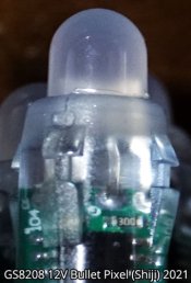
One of Ryans photos above seems to show a 300R resistor but it's hard to read.

Close up of GS8208 12V bullet bought from Shiji 2021
 

TerryK

Retired Elf
Joined
Feb 9, 2020
Messages
655
Location
West Central Ohio
Another thought regarding the resistor. Though the chip's datasheet does not indicate (needing) one, it could be an impedance matching resistor on the chip's DI (to help prevent data line signal reflections similar to what is used with a WS2811). A schematic or partial schematic would help clarify.
 

AussiePhil

Dedicated elf
Administrator
Joined
Jun 20, 2009
Messages
1,606
Location
Canberra, ACT, Australia
Another thought regarding the resistor. Though the chip's datasheet does not indicate (needing) one, it could be an impedance matching resistor on the chip's DI (to help prevent data line signal reflections similar to what is used with a WS2811). A schematic or partial schematic would help clarify.
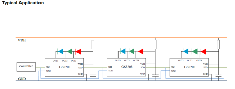
The typical application diagram in the datasheet shows the resistor just not the value to be used.
Capture.PNG
 

Skymaster

Crazy elf
Global moderator
Generous elf
Joined
Dec 19, 2021
Messages
1,042
Location
Western Sydney
In the 'Electrical Characteristics' table of the data sheet, there is a value for Rvdh of 50 ohms minimum (or typical, the headings are stuffed), on a 12V supply, and Cvdh of 0.1uF.
Nothing else mentioned though.

That would limit total current of the circuit to 240mA; should the IC fall short-circuit, which is still 5 times what it needs to be.

I'm guessing the fixed resistance is used to form a divider with the internal IC resistance during PWM, to minimise the amount of dissipation the IC needs to perform when all lights are on, as the IC is limited to 150mW dissipation, with any excess being dissipated in the resistor.
 

TerryK

Retired Elf
Joined
Feb 9, 2020
Messages
655
Location
West Central Ohio
Hmm. Oops. I missed those in the datasheet. Typical value for the resistor, minimum value for the capacitor I think.

I would not rule out the divider theory but am somewhat skeptical as the internal constant current source should handle the LED load and the internal 7805 the logic portion. I'm more inclined to revert to my first thought, filtering of switching noise. However without knowing more of what's inside the IC it is mostly making educated guesses.

Short circuit failure might be a problem. Twelve volts across 30 Ohms works out to a little under 5 Watt. Something will warm up rather quickly.
 
Top