ACL Strobe Building

kenlmcse

Lightshowpro Developer
Joined
Feb 21, 2011
Messages
23
Location
Gilbertsville, PA
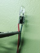
I followed the pdf on the WIKI, Finished one all the way till the end, including hot glue...

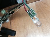
Now only 143 more to go

These boards are small!

VERY BRIGHT LIGHTS!
 

drlucas

Apprentice elf
Joined
Jul 31, 2013
Messages
58
I connected one I just built to a 5v power supply and waited 10seconds. Nothing happened. Looks like my +\- are connected right and no solder bridges. Is there a trick to get them to start firing. I don't have it connected to a ray27 or anything. Just power supply.
 

AAH

I love blinky lights :)
Community project designer
Joined
Dec 27, 2010
Messages
4,188
Location
Eaglehawk
Can you pop a photo up of both sides of the board. My immediate guess is that maybe the led is around the wrong way.
 

drlucas

Apprentice elf
Joined
Jul 31, 2013
Messages
58
Here you go!
 

Attachments

  • image2.JPG
    image2.JPG
    1.6 MB · Views: 71
  • image1.JPG
    image1.JPG
    1.2 MB · Views: 70

AAH

I love blinky lights :)
Community project designer
Joined
Dec 27, 2010
Messages
4,188
Location
Eaglehawk
Led and wires are on the wrong ends. Leds should be on the end with the larger IC. Wires on the end with the smaller IC.
 

drlucas

Apprentice elf
Joined
Jul 31, 2013
Messages
58
Oh...they don't go through hole?! They line up so nicely. I'll fix and test tomorrow - thanks - that's what I get for not really reading the manual
 

drlucas

Apprentice elf
Joined
Jul 31, 2013
Messages
58
Well after looking more carefully at the wiki manual I see what I did wrong. I tried to build one up last night but it didn't fire at all.

On the chip side of the board there is a + and a - am I supposed to connect the + to the edge where the white box is or beside it? I am currently beside it as I assumed the white box indicated pin 1 for the header if I was to flash the pic later on. Also does it matter which side of the board the power leads are connected? The chip or the resistor side?
 

AAH

I love blinky lights :)
Community project designer
Joined
Dec 27, 2010
Messages
4,188
Location
Eaglehawk
On the chip side the + is closest to the strip of 5 holes that is for the ICSP programming header. It's actually the pad in the middle of the bottom edge that is the + for the incoming power. Either side of the pcb can be used for the in and either side for the out. The latter version of the assembly guide is at the bottom of http://auschristmaslighting.com/forums/index.php?topic=6458.msg57529#msg57529 . I will change the version that is on the wiki later today.
 

drlucas

Apprentice elf
Joined
Jul 31, 2013
Messages
58
Ok. So maybe my power supply is marked wrong. I swap power and the strobe turns on solid white. Should it strobe on its own? When i reverse polarity nothing happens. Did I previously just kill my pic with the reverse and have to solder up another to test or is the light a sign of goodness and I need to use something else to control it.
 

dougd

Full time elf
Joined
Jan 24, 2012
Messages
135
Location
Cleveland, Tennessee
Here is how i did mine. Had 1 or 2 fails out of my 96 strobes.


Put the resistor in on the non chip side.


Soldier it on the same side. Soldier might fill the plus side of the + 5 volts.


Next clip the short side of the led 1/8 inch past the wide part.


Cut the longer side 1/4 past the wide part.


Tin the 2 pads on the non chip side where the led soldiers to.


Soldier the led to the board paying attention to + and -


Soldier a green wire to the - side of the board opposite the LED.


Soldier a red wire to the + side again opposite side of the board as the LED.


Hook red wire to +5 volts and the green wire to - side 5 volts.


Stobeing should start immediately.
 

drlucas

Apprentice elf
Joined
Jul 31, 2013
Messages
58
Ok. Multimeter is coming out tomorrow (or maybe Saturday as I am going to likely park the strobes for Halloween and focus on some much needed sequencing !!)
 
Top