For moving props it's sometimes desirable to use a linear actuator to move a prop up/down, in/out etc. The term linear actuator is often shortened to Linak but this is actually a brand name.
The wiring diagrams attached are for a linear actuator that has built in end switches. ie when you power them and they get to the end of the stroke they have a switch internal to them that cuts off power.
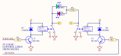
When controlling relays the output of the DC dimmer must be controlled with a 0% or 100% signal with no global dimming in effect via an E1.31 board or the sequencer.
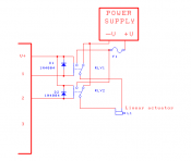
The 2 relay control method allows the linear actuator to be moved part of the stroke controlled by how long the output is turned on for. The outputs would be labelled as extend and retract or up and down or similar. Turning off the extend or retract output will leave the actuator where it is.
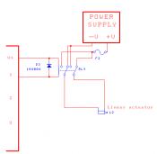
The single relay control method only allows a fully extended or fully retracted control. As soon as power is supplied via turning on the output the actuator will start moving and will continue moving until it hits the end of it's stroke or power is turned off via turning off the output. As soon as power is removed from the output the actuator will retract until it reached the end of it's stroke.
The 1N4004 diodes are required to prevent the back EMF (coil spike) from damaging the mosfet output transistor/s of the dimmer.
The extend or retract can be swapped by changing the 2 wires going to the actuator.
The same power supply can be powering the dimmer pcb as the actuator or alternately a different power supply could be used.
The relay needs to be the same voltage as whatever is powering the dimmer pcb.
The fuse should be sized to suit the actuator.
The wiring diagrams attached are for a linear actuator that has built in end switches. ie when you power them and they get to the end of the stroke they have a switch internal to them that cuts off power.
When controlling relays the output of the DC dimmer must be controlled with a 0% or 100% signal with no global dimming in effect via an E1.31 board or the sequencer.
The 2 relay control method allows the linear actuator to be moved part of the stroke controlled by how long the output is turned on for. The outputs would be labelled as extend and retract or up and down or similar. Turning off the extend or retract output will leave the actuator where it is.
The single relay control method only allows a fully extended or fully retracted control. As soon as power is supplied via turning on the output the actuator will start moving and will continue moving until it hits the end of it's stroke or power is turned off via turning off the output. As soon as power is removed from the output the actuator will retract until it reached the end of it's stroke.
The 1N4004 diodes are required to prevent the back EMF (coil spike) from damaging the mosfet output transistor/s of the dimmer.
The extend or retract can be swapped by changing the 2 wires going to the actuator.
The same power supply can be powering the dimmer pcb as the actuator or alternately a different power supply could be used.
The relay needs to be the same voltage as whatever is powering the dimmer pcb.
The fuse should be sized to suit the actuator.