Installing a Kulp on an existing 16 strip array. Can I create a matrix?

Markjacks

New elf
Joined
Jun 5, 2024
Messages
18
That's great...too bad I jumped the gun and reset everything but I will go at it again tomorrow when I link back to the controller. I sincerely appreciate your help with this because I was pretty lost and there's a show coming up. I'll keep you up to date on my progress.
 

Markjacks

New elf
Joined
Jun 5, 2024
Messages
18
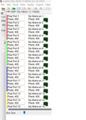
Skymaster...I believe I got the ports set up properly now. Thank you so much. If you understand the difference between ports and channels you have my great respect. I am not there yet.

I'm now struggling to get a text effect up on the LED panel. I've watched a lot of Youtubes but still missing some link in the chain.

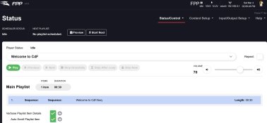
So I am getting the test pattern to run and my sequence is apparently on the Falcon but I am stuck on making the transition to getting the sequence actually on the LED panel.

Can you suggest anything?
 

Attachments

  • Populated Ports.jpg
    Populated Ports.jpg
    619.8 KB · Views: 12
  • Play.jpg
    Play.jpg
    425.2 KB · Views: 12
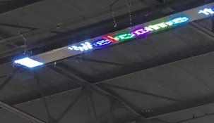
  • Pixel panel in ceiling.jpg
    Pixel panel in ceiling.jpg
    1.3 MB · Views: 12
Last edited:

Indigogyre

Journeyman Elf
Generous elf
Joined
Jun 26, 2021
Messages
468
How did you get the sequence onto the FPP instance? Did you manually copy it there or did you use FPP connect?
 

Skymaster

Crazy elf
Global moderator
Generous elf
Joined
Dec 19, 2021
Messages
1,203
Location
Western Sydney
A port is an outlet on a controller that sends data to a run of pixels. These are physical electrical connections.

That data running over each port is made up of multiple channels, 3 for every distinct pixel, one containing each the Red Green and Blue data.

So a port which has 120 pixels attached needs 360 channels of data to be able to individually control each colour.

**Nb yes there are pixels that use more channels, such as rgbw and 16 bit pixels but we're not getting into that here
 

MikeKrebs

Full time elf
Joined
Dec 8, 2014
Messages
186
You should jump into the zoom "right now" and see if someone can help you out. With your time sensitive task, you need people who can walk you through the pieces. Be close to your hardware and click the zoom meeting on https://xlights.org/
 

Markjacks

New elf
Joined
Jun 5, 2024
Messages
18
Okay! I got my ports populated! Thanks for the explanation of how ports are different from channels. That will help me a lot. It is good to know what the terms mean. Also thanks for the link to the Zoom Room. I see people referring to it but I didn't know how to get there.

I've moved on to putting text up on my matrix. I actually got it to work but it is mirror image upside down. I guess it is either because of the order I wired the strips into the channels on the board or some setting. Anyway I'm not quite sure how to correct it. Someone on line said just reverse the Y-axis but I can't find a place to do that. Here's a picture of the array running a test pattern. I forgot to get a picture of the weird text but I'll snap one tomorrow.

I was wondering if you have any clues of how to straighten out the text.

Thanks again for your assistance.
 

Attachments

  • Pixel panel in ceiling.jpg
    Pixel panel in ceiling.jpg
    1.3 MB · Views: 10
Last edited:

Skymaster

Crazy elf
Global moderator
Generous elf
Joined
Dec 19, 2021
Messages
1,203
Location
Western Sydney
Check the matrix model - you can set where the wiring starts - top left, bottom left, top right, bottom right.
My guess is you need to change top-left to bottom left.
Push your config, re-render and upload.
 

Markjacks

New elf
Joined
Jun 5, 2024
Messages
18
Wow that was so easy! I changed it to bottom left and I'm in business. Thanks a lot for that! I've just got "ONE" more little problem. I'm getting some weird anomaly at the far left. It's the first few pixels of each port. They are flashing rapidly except for 1 and 16 which appear to be on steady it looks like. I have tried to figure it out but maybe one of you guys knows exactly what it is. Could there be another sequence running in the background? I hate to start over because I have it working so well now.
 

Attachments

  • PXL_20240722_030432329.jpg
    PXL_20240722_030432329.jpg
    261.3 KB · Views: 14
Last edited:

Markjacks

New elf
Joined
Jun 5, 2024
Messages
18
When I first hooked up to the Falcon I was using different pigtails than I had used in the past which had a different wire color configuration. Not realizing it I hooked all ports up in reverse polarity. Could this have toasted the first WS2811 chips? On the other hand it kind of looks like a pattern. I wasn't able to show it well in the photo but port 1 and 16 are on steady and 2 thru 15 are flashing rapidly like you shouldn't look at if you have epilepsy. The boss says just throw a black towel over it but I was hoping for something more elegant.
 

Indigogyre

Journeyman Elf
Generous elf
Joined
Jun 26, 2021
Messages
468
Are those white lights at the start of the strip or the end? I also get the feeling there might be some channel overlap if you flipped the model and maybe multiple model over lays were created.
 

Markjacks

New elf
Joined
Jun 5, 2024
Messages
18
I don't think you toasted it.
How long are the pigtails / cables to the matrix? Just the left end flashing or the whole strip?
I don't think you toasted it.
How long are the pigtails / cables to the matrix? Just the left end flashing or the whole strip?
PXL_20240722_030432329.jpg
The pigtails are only 6 inches at the most. Just the left end flashing. It is the starting end of each strip. Sorry I don't have a better picture than this.
Are those white lights at the start of the strip or the end? I also get the feeling there might be some channel overlap if you flipped the model and maybe multiple model over lays were created.
I did flip it to Bottom Left. How can I check if there are multiple model overlays?
 

Indigogyre

Journeyman Elf
Generous elf
Joined
Jun 26, 2021
Messages
468
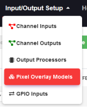
pixeloverlay.png

Personally, I would delete all the model overlays and upload the sequence once more to recreate the proper overlay.

FPP Connect
fppconnect.png
 

merryoncherry

Senior elf
Generous elf
Joined
Apr 2, 2022
Messages
676
Location
Cherry St., Hudson MA USA
I doubt the overlap or incorrect setup idea because you only have one model, right?
Maybe I shouldn't have been so quick to say that you didn't toast it. Some of these strips have a voltage converter per segment, does the issue happen to line up with the cuttable segment of strip?
Blacking it out not the worst idea.
 

Markjacks

New elf
Joined
Jun 5, 2024
Messages
18
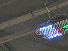
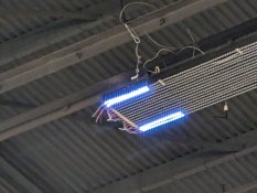
Here's another picture while it's running. If they are toast they are only toasted lightly brown because there is still something going on there. I am going to try to follow up on the model overlays idea. I am extremely new to this stuff. I didn't think I had anything but one sequence of text running but maybe there is something else. It would probably be good also to just start over since I;ve learned a lot in the past few days.

The second picture is of the matrix with no sequences running. I see that it is actually ports 1 and 2 and 15 and16. I had added those 4 ports/strips this year because when I upgraded from and ESP32 to a Falcon controller I had 4 more ports to use.

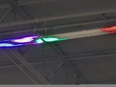
I have also tried a different sequence and I noticed the pixels in the 1,2,15,16 strips are delayed and offset for example the colored circles in the 3rd picture.

Could it be the chips in the 4 strips have a millisecond delay?
 

Attachments

  • PXL_20240724_001730239.jpg
    PXL_20240724_001730239.jpg
    526.6 KB · Views: 8
  • PXL_20240724_004251531 (1).jpg
    PXL_20240724_004251531 (1).jpg
    564.1 KB · Views: 3
  • PXL_20240724_005355612.jpg
    PXL_20240724_005355612.jpg
    521.6 KB · Views: 3
Last edited:
Top