Running xLights Sequence on Raspberry Pi (And maybe an ESP device?)

GR9

New elf
Joined
Dec 11, 2023
Messages
43
Hello!

Before going any further, I want to say that I really don't know what I am doing, I am just making guesses based on the information from my 50 open tabs of research. I just started looking into this hobby a few weeks ago, and want to try and get things working to see what is possible (With the end goal of maybe having a small setup for next Christmas). If I have anything wrong (Or make an incorrect assumption somewhere), please let me know!

That said, here is what I have ordered (As I assume it is important to my later questions lol):
- AC 110V/220V to DC 12V 30A 360W Universal Regulated Switching Power Supply Transformer (And the power cord)
- ALITOVE 500pcs WS2811 Individually Addressable RGB LED Pixels Light 12mm Round Diffused Digital Color Changing LED Module Light DC 12V
- Raspberry pi 4b 4GB RAM (And a good 64GB SD card)

Also, I have downloaded the xLights software, and am starting to get a hang of setting up scenes and such (Bypassing all the of controller stuff since that's the part I am stuck on).

My original idea going into this was to use the Raspberry Pi running FPP, getting the data from xLights somehow (So xLights wirelessly transfers the data to the Pi when the sequence is ready, then FPP runs it at the specified intervals). Doing some research, I found that the Pi needs to use the PWM pins for the data, which is only has two of (GPIO18/19). So new thought is to run the lights off of the two PWM pins on the Raspberry Pi(source) in two strands (So about 250 lights on each pin). Would this be possible to do? Everything I have seen online wants you to connect the Pi to a separate controller, but I don't really want to spend a ton more money on one. I don't mind injecting power if that is an issue.

I kind of had a feeling that 250 lights would not be able to run off each of the Pi's pins (And if they could, scalability will certainly become an issue at some point, right?), so I started looking into different ways to get around having to drop $200+ on a dedicated controller board (One other thing I forgot to mention, all the hardware I am buying I want to repurpose into something else if this does not work / I get too annoyed at it. So Raspberry Pi's, power supplies are OK, but dedicated PCB's should be avoided).

I found a mention to using the ESP32 to control some lights, and the Raspberry Pi as the main device. I had trouble finding anything else about this, including how this would have to be setup (Would something have to be done in xLights?). Assuming using the ESP32 to control the light strings using data from the main Pi, how many lights across how many pins could it handle? (Yet an another side note, I am OK with making a custom PCB for this if needed. Those are pretty cheap, and actually kind of fun to create). I saw a mention for a HAT being needed for the ESP, but the sole reply to the topic linked at the beginning of this paragraph makes me think I can just buy a plain ESP dev board (Like this one), somehow install FPP on it and get it linked to the primary Pi.

EDIT: I also found this mention about using the ESP8266. Reply #2 mentions a NodeMCU needed for this to work, and an optional HAT? Would this be another option as well? Since the ESP32 discussion does not mention anything like this, can it just be ran out-of-the-box, or is additional hardware / special kind of hardware needed for that too? If you can't tell, I am really confused lol.

---

TL; DR: How can I get a Christmas light setup using Raspberry Pi and NOT a dedicated controller board like the falcon F4?

So hopefully that makes sense! Please let me know if you have any questions for me, and please let me know if I got something wrong. Any help with deciding what to do regarding controller boards, and if anything special needs to be done in xLights / while setting up FPP for this to work would be greatly appreciated!

Thank you an advance, and Happy Holidays!
 
Last edited:
You can certainly use the two pwm pins with FPP, it's how all the external hats like PiCap and the Hanson RPi28D+ work.
https://www.hansonelectronics.com.au/product/rpi-28dplus/

They are just basically level shifters to take the 3.3V GPIO and convert it to 5V data signal. They do prices a few other things, such as fused power and DMX outputs, for example, and are often quite reasonably priced.
Pixels will run off the 3.3V signal, but the first pixel needs to be really close (say within 30cm/ 1 foot) of the pin.


There limitation of number of pixels is two fold. Firstly there is the data rate. WS281x pixels can run a huge number in a string but it comes down to frame rate. At 40fps, the maximum is around 800px. At 20fps, that goes to about 1600fps. FPP can work up to this limit, Per Output, so 1600/3200 pixels total on the two GPIO pins. Different controllers have other limits based on memory, their architecture etc that will give a lower number than this.
Secondly there is power. No controller can provider enough power to control the entire maximum limit off pixels, you'll always need to add more with power injection in this case.

When I first started playing with pixels and a Pi, I had them directly wired as above, GPIO 18 to the data in, and external power.

ESP32s etc have the same limitations, although they're CPUs are slower and would also be a limiting factor.

A big advantage of using the Pi and FPP is you get all the show player built in. I've your sequences are programmed and loaded up, xLights is no longer in the picture for running the actual show.
 
  • Like
Reactions: GR9
Hello

Thank you for your reply!

I want to make sure I understood you correctly here, and I have another question as well :)

Since it would be nice to have the lights start a bit further away from the Pi, can I use a converter (like this one) to move from the 3.3v outputted by the Pi to the 5v needed by the lights?

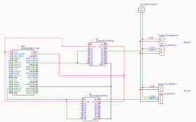
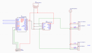
Here is a schematic I came up with for using the Pi, and that converter. Does it look like something that could work?
(Please ignore all the horrible stuff that is probably going on with the coloring. I've only created schematic's for my own use before, so I am not really sure of the 'right' way to make them).
1703362924619.png

As for my other question, could I use the ESP (Or something like a Raspberry Pi Pico W) to run additional lights? For example, plug the Pi and it's two strings into one spot, and have a few ESP/Pico's around the yard controlling additional strings.

Thank you again for your help!
 
Yeah thats basically it. On the buffer chips, however, wire the OE to always be on. Don't connect it to the data line otherwise you'll be getting zeros and unknown, or 1s and unknown, not 1s and 0s as the outputs will be left floating in one state (depending on whether the line is active high or low).

Yes the ESPs can be used, same circuitry used for level shifting. The Pi can then stream DDP/E1.31 out to the ESP for rendering. Using ESPixelStick or WLED firmware is the way to go.
That being said, it's preferable to use ethernet over wifi when streaming data as you may get lag if the wireless has not been correctly configured.
 
  • Like
Reactions: GR9
When I fist started testing this hobby I bought a couple Dig-Uno and a Dig-Quad esp32 based controller. They're fairly inexpensive to start with and can handle wled and xlights also. There are also other esp32 based controllers out there that work with xLights but it's what I know. I realized that for what I wanted dedicated controllers would be best and moved up. I still will use the Dig-Uno to test pixels and run some misc. things here and there when needed.
 
Thanks so much for the help guys.

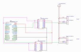
I think I got the schematic fixed, but just going to paste it here in case I screwed up something simple (All I did is wire the OE into the 3.3v input line instead - it is now pink instead of green).

1703372943032.png


You also mentioned "The Pi can then stream DDP/E1.31 out to the ESP for rendering. Using ESPixelStick or WLED firmware is the way to go". Few questions here:
1. I am assuming this stream would be something that is setup in FPP, and as long as the two devices are connected, and the IP of the secondary is known by the FPP instance on the primary, it should work, correct?
2. Also assuming that the firmware you mentioned is to be installed on the Pico/ESP, correct?

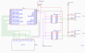
Since the Pico W will be able to do the job just as well as the ESP, I think I will use it as I already own a few of them, and can get more if need-be. I went ahead and drew up a schematic for the pico diagram as well.

For the Pico, it does not have a ethernet port, so I found an adapter that could work (Potentially stupid question, but I wire both the primary Pi, and the Pico's directly into my router, correct?). Question is, would it work with ESPixelStick/WLED out-of-the-box, or would I need some custom firmware on top of it? (Source). Also, I saw that there are multiple PWM ports for the Pico, so how many different output could it have? (Source).


1703374726952.png
(Once again, 5V and 20V are red, 3.3V is pink, data is green, and unknown is blue).

For the 5v USB IN for the Pico (U7), I was looking at these guys. Just throwing it in here in case it is needed.

Thanks!
 
Last edited:
You only need one buffer chip per device. They are 8 channel units. Connect GPIO 18 to A1, and GPIO19 to A2. Then B1 connects to output 1, and B2 connects to output 2.

For the ESPs, you should be able to support 4 outputs at minimum. Again, connect these 4 GPIOs to A1-A4, and then the pixels to B1-B4. The GPIOs are defined in software. For compatibility, you can mirror the DigQuad GPIOs - 16/3/1/4 for outputs 1-4 respectively - https://quinled.info/quinled-dig-quad-pinout-guide/

1. I am assuming this stream would be something that is setup in FPP, and as long as the two devices are connected, and the IP of the secondary is known by the FPP instance on the primary, it should work, correct?
2. Also assuming that the firmware you mentioned is to be installed on the Pico/ESP, correct?

Since the Pico W will be able to do the job just as well as the ESP, I think I will use it as I already own a few of them, and can get more if need-be. I went ahead and drew up a schematic for the pico diagram as well.

1. Correct
2. Correct, however the RPI Pico is NOT supported by ESPixelStick / WLED software I believe. You would be on your own with that one.
 
  • Like
Reactions: GR9
Alright, thanks for that info.

Looking at some GH issues other users have bought up about RPI Pico support, I think I am going to change course on that decision and go back to the ESP.

Since both the ESP32 and ESP8266 seem to be used for this, which one would you recommend for my use case? Also, is there a good ethernet shield (Would the one I linked before, this guy, work?)

You only need one buffer chip per device.
Gotcha, that makes complete sense. I also came across a site that plugged the ground into all the unused ports on the buffer chip, do I need to do that?

Thanks!

EDIT: One other piece of information, I think I am going to use WLED, it looks a tad easier to setup. Assuming it works just as well (And connects just as easily) with connecting to FPP that is.
 
Last edited:
I would look at the WT32-ETH01 ESP32 module. The ethernet is supported out of the box by WLED, and you can pick up the modules for quite cheap.
The ESP32 kills the 8266 on performance and so you'll get much more running off them.

On the buffers, Linking the unused outputs to either ground or VCC forces them into a known logic state so that there aren't sitting in lala land as far as logic levels go, potentially flapping and causing interference.

No issues using WLED and xLights/FPP ... Many folk including myself use it
 
  • Like
Reactions: GR9
WT32-ETH01 ESP32 module
Woah, that is quite a bit more then the base ESP32. Suppose I would save time not attaching the ethernet separately though. Would all of this one (#1), this one (#2) and this one (#3) work?

For the buffer board, I linked the "A" side to the GND and left the "B" side open.

Assuming I buy one of the ESP32's linked above, I just plug the ethernet right into my router, correct?

Since the bord does not have a USB, I know I'll need a serial adapter for it, but this one here has three different options (And I would think the one I buy matters, right?). Lastly, I can't find a good English pinout, and I must be using the wrong search terms, but I cannot find what pins I would connect the LED data to (What pins are PWM compatible?). The link you shared just has N/A for a bunch of stuff under the 8266 column, does that mean I can only use IO1, IO2, and IO3 for the data output?

Thanks!

(Flashing video - Putting this link here so I have it as I know I will come back to this topic later :) )
 
If you use the txs0108eqpwrq1, you probably need to read this one over again (I think this is the one mentioned that said to ground unused pins). The OP ended up changing to a SN74AHCT125. I seem to remember other posts on the txs0108eqpwrq1 that were along the similar lines. For ws2811 and blinky flashy, we have a long history with the SN74AHCT125. But if you use the tx chip and get it to work, would love to see the end result.
 
Thanks for sharing that. I think I’ll switch to the SN chip since I don’t feel like trying to get the hardware to work, I’m more of a software person. I think I’ll go with this guy for the chip.

Using the WT32-ETH01, I am assuming using 5v to power it (With something like this) would be recommended, right?

Lastly, I am still confused here:
I cannot find what pins I would connect the LED data to (What pins are PWM compatible?). The link you shared just has N/A for a bunch of stuff under the 8266 column, does that mean I can only use IO1, IO2, and IO3 for the data output?

Thanks again for your help!

EDIT:

In clearer terms, I am confused as to what pins I can use on the WT32-ETH01 board as data lines, and how many pixels each pin would support running.

I also thought up on other question: Can I use the two PWM GPIO pins on the original Pi, as well as whatever pins can be used on the WT32-ETH01 at the same time? So having two data lines from the pi (One on each PWM pin), and x data lines from the WT32-ETH01 (Where x is the number of supported pins); Is that possible?

EDIT 2: I came across this thread questioning the stability to the W32-ETH01, is this something anyone here can corroborate or deny? https://wled.discourse.group/t/wt32-eth01-lan-wifi-flash-tutorial/2786/22

EDIT 3:

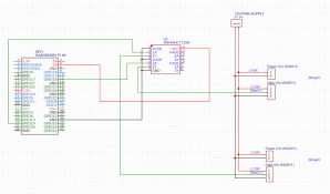
Here are the updated schematics with the new chips. Red is 5v or 12v, green is data, back is ground, blue is unknown.

Primary Pi:
1703455287553.png

WT32-ETH01 (Can potentially add two more data outputs if all the IO ports I have linked in blue can output the data correctly):
1703455308142.png
 
Last edited:
The RPi with FPP can output pixel data on two lines and send data to other controllers all at the same time. So, you would use FPP to be a player (device that plays your show) and output to any other controllers that need and if they are "remotes" send sync packets to those controllers.

I don't have a WT32 but Wasatch Pixels has been selling controllers with them for a couple of years unfortunately with zero reviews so we don't know much about how they are working out.

If you use the RPi or the WT32 as depicted, you need to tie the grounds (V-) between the data 5v and 12v sides. The pixels need the "same reference" to figure out the on and off (ones and zeros). Following the link about the problem to some further reading suggested decoupling caps on the 74hct device. Someone with electronics knowledge should chime in - I can research but I don't know the ins and out of this. I have seen with the Raspberry pico devices that someone built one without the caps.

For pins, you might look at the quinled esp32 based ethernet controller, the WLED software and the Wasatch pixel products (these would be the closest). I found a couple of videos that talked about loading wled on wt32 devices but they only had one output. So, not sure which pins are unused and available as the pixel pins.
 
Thanks for the info, and Merry Christmas! I’ll update my schematics and share them with you when I get the chance.


further reading suggested decoupling caps on the 74hct device
Could you share the link you found suggesting this? I would love to take a look.
 
Back
Top