Running xLights Sequence on Raspberry Pi (And maybe an ESP device?)

if using xLights you will create your sequences, define your controllers and run FPP Connect. FPP Connect will send a configuration to the ESPixelStickV4 based controller and then it will create special versions of your sequences and send those to the ESP.
What I currently do is upload the fseq file from the xLights show directory into FPP, then click the “Play” button. So I will have to run FPP connect before exporting that fseq file, or after it is already in FPP?

For the LoLin, I found this reference to using an external antenna, but not sure if it will work (I also don’t know what resistor they are talking about. Is that a pin I need to ground)? https://forum.esp32.com/viewtopic.php?t=9539

Thanks!
 
The fseq file you put on the FPP show player is VERY different than the fseq file that goes on the ESP. The ESP uses what is called an "uncompressed" "sparse" fseq file. xLights generates those files when running FPP Connect. Vixen does it in Export. FPP has a command line utility to create the file.

If the D32 board has the pads then yes, you can move the resistor from pads R13<->R14 and solder on an SMD socket. Do you have an SMD oven or an iron with a needle tip? Also a good magnifier and lots of light.
 
Do you have an SMD oven or an iron with a needle tip? Also a good magnifier and lots of light.
Only got the light unfortunately. There is no other way to extend the internal antenna?

Unless you think it would work going 200ish ft though a few walls.

Other thing I can think of is just putting it closer to the house and running a longer data line. Could I run a bunch of CAT5 cable for data after converting it to 5v?
 
Thanks for the link. Just to make sure I got it right, I want the C3 version, correct? I am assuming the singer thing on the right is for the SD card.

For the Data and DC Ground (For DC, is “ground” or “negative” the correct term?) pair in CAT5, 10m / 32ft should be good enough.


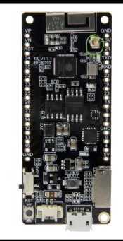
TTGO T8 External Antenna version. Then change the resistor and things are simpler
if it is already an external antenna, why would I have to change the resistor?
 
Gotcha.
On the product image, I see the port (circled in green), but not a resistor.
IMG_3607.jpeg

For the antenna, this looks like it will work, but can you confirm (The 15cm length)?


Lastly, I want to make sure I got the right T8 board here as the link you shared has multiple options:

Just to make sure I got it right, I want the C3 version, correct?

Thanks!
 
What I currently do is upload the fseq file from the xLights show directory into FPP, then click the “Play” button.
You can use FPP Connect to do this for you, as well as sweet to and UDP outputs for DDP/E1.31 controllers, and create the models within FPP for testing purposes. It will also configure pixel outputs you may have connected to your Pi when using it as a direct controller.
Sequences uploaded using this method can automatically be added to playlists, and the associated media files get uploaded too.
As Martin mentioned, the FSEQ file can be different per device. Both in format and in the data that it contains. By using sparse files, each instance (...of FPP, ESPixelStick etc) only has the appropriate information it needs for the pixels it is driving, and not the rest of the show, minimising file sizes and decoding effort needed on the device.

FPP connect can also push to all the appropriate controllers simultaneously, and make sure each have the correct information they need.

The manual uploading of files can be cumbersome when dealing with multiple devices, especially when they all need different formats, AND have the same file name.
I would not recommend using the manual mode with xLights, unless you have a very esoteric configuration which makes it impossible to use.
 
You will have to go to the MFG page for instructions on how to use the external antenna.
Sorry to bother you, but can you share a link for this one? Everything I see if for the original one, and I don’t get any relevant results when adding “MFG” to my search.

Also, is using fuses with this board a good idea? I have some 7A ones in my cart from before, but don’t know where to put them.

Thanks again!
 
A little late to the party, but my setup follows your essential premise: A Raspberry Pi and some off-the-shelf Microcontrollers to drive lights.

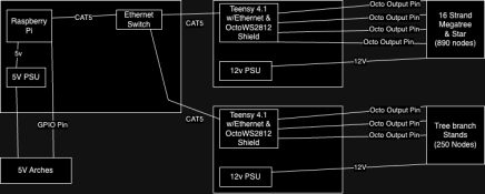
Here's a thrown-together Diagram:
LightDisplayLayout.png

I've got my control box, which contains:
  • Raspberry Pi 3 running FPP.
  • A 5V PSU (For the Pi, and to drive 5V elements in my show)
  • An Ethernet switch (To connect other elements to FPP)
Then I have two satellite control boxes that contain essentially same thing:
  • A Teensy 4.1 (this is a Microcontroller module, not unlike an ESP32 module. It has support for Ethernet onboard)
    • The ethernet Adapter for the Teensy
    • An OctoWS2812 adapter (this breaks out and level shifts the GPIO)
    • A DC-DC converter to get 5v for the Teensy
  • A 12V 30A PSU (I use Meanwell)
  • A some terminal blocks for distribution
  • All the relevant cables for connecting lights/power injection, etc.
The Ethernet support on the Teensys was the big selling point for me. Wifi can be hit or miss, and may not give you good synchronization between your elements. I imagine there's a way to get the Pi to talk to a module (like the ESP32) over Serial or some such but the networking stuff is built right into FPP, and the firmware to provide and E1.31 protocol running on the Teensys is open source - basically you hard code the IP address, and set the pins, and write it with the Arduino IDE.

For the satelite control boxes, I estimate I spend about $100.
  • The Teensy, OctoWS2812, and ethernet adapter are just over $45 USD.
  • The Meanwell 12v PSU is $33 USD
  • The Terminal blocks are $10
  • And there are probably some wires, crimped connectors, etc in there as well.
This of course, does not account for the cost of the lights themselves, and the pigtails to connect to the lights from the box.

Also, as noted in the diagram, I do have some arches that are around 60 nodes each that get signal from the Raspberry Pi directly. They're 5v powered. The Pi 3 has 2 PWM pins it can use for driving lights, and I've successfully driven 300 Nodes without issue (though you desperately need power injection with 5V)

I did a writeup on this setup from a couple of years ago (one satellite box is a new addition this year) here: https://aaroneiche.com/2022/07/01/christmas-lights-2021/
 
Last edited:
One comment on the latest schematic. It looks like you put the caps on the SN74HCT125 in series and they should be in parallel. That is between power and ground.
 
EDIT 2: I came across this thread questioning the stability to the W32-ETH01, is this something anyone here can corroborate or deny? https://wled.discourse.group/t/wt32-eth01-lan-wifi-flash-tutorial/2786/22
I know im late as well for any of this and yes i found that thread on the stability of the WT32-ETH01

but just wanted to say this...

I ran approx half my show on 2 x WT32-ETH01 this year without any issues (other half was 2 x DigOctas) using WLED 0.13.0-b3 across all of them

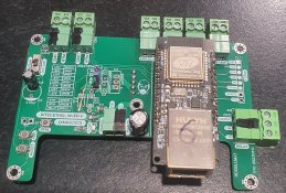
I designed and built a BOB for my WT32-ETH01's (PCB designed in EASYEDA & manufactured by JLCPCB and the components i soldered myself) and crash tested everything a lot before xmas - i did have one of my boards play up, but that was a surface mount soldering issue (my fault) and was fixed.
Did my research and took advice from that thread and others about the stability but apparently my miles did vary and i didnt have any issues (or i just had the right combo of capacitors on my circuit haha).

i had to create all this as my budget was low after i purchased the 2x DigOctas and the the 8500 pixels for xmas2023 and is in no way a commercial product, it's just bragging rights LOL.

Features of my BOB
8 x ports
1 x relay
1 x spare I/O
2 x buttons (butt 1 on pcb and butt1 & 2 on connectors)
1 x reset button
1 x program button
1 x flash port (i use an esp8266 to program it with WLED using https://install.wled.me/ to upload)
(Yes, inspiration was taken from the digoctas, even the shape of the PCB)

level shifter is an HB245 SMD (SN74AHCT245PWR) underneath + resistors


273971373-31deea6f-ea08-40a9-931f-96036db1f88f.jpg


LED1 GPIO33
LED2 GPIO5
LED3 GPIO17
LED4 GPIO2
LED5 GPIO4
LED6 GPIO12
LED7 GPIO14
LED8 GPIO15
Relay GPIO32
Spare GPIO39
BTN1 GPIO35
BTN2 GPIO36

so really this board can do 10 ports if you use relay and spare i/o as LED pins

quinled details how many pixels you can have on one port on an esp32

What is the max amount of Addressable LEDs per controller?

but generally i chose <= 800 each port as it will get you xlights 40fps (based on above page)

I know you didnt ask but... my setup was :-
1 x WT32 (5748 channels) 1x mega tree, 1x mega star, 4x mini trees + star, 1x snowflake, 1x house vertical, gutter string and a drive way run
1 x WT32 (7200 channels) 60x40 matrix (2400 seed pixels, 3x ports)
1 x DigOcta (9189 channels) 6x arches, 5x arch verticals, 3x house verticals, 3x snowflakes, 2x window outlines, 1x drive run, 1x showstopper spinner
1 x DigOcta (4209 channels) 1x window outline, 1x house vertical, 1x garage outline, 3x roof outlines, 2x signing trees, 1x snowflake

I have a controller config for xlights for my WT32s using WLED so the visualiser "upload output" was seemless.
TBH i had some issues with the DigOctas - when uploading a config change - it would take the config and sometimes just boot loop, required power off / on to recover but otherwise solid kit!

So WT32-ETH01 is quite capable and my 2023 xmas show is evidence, they got me through and gave me a good taste of what you all have had for years now...

TY for listening and i'm done.
 
The Ethernet support on the Teensys was the big selling point for me. Wifi can be hit or miss, and may not give you good synchronization between your elements.
That is my biggest worry when buying the microcontrollers. Did you have lag experience using WiFi? Martin mentioned that the PixelStick firmware over WiFi is good, but Ethernet should be used for WLED. Does this kind of match any experience you have?

Also, a question regarding the setup you described: Is the Pi connected via Ethernet to your home network, or is that a WiFi connection? If it is a WiFi connection, I’m assuming the Pi can understand that the two Teensy’s are hardwired and use that connection over a wireless one.
The blog post was a good read as well, thanks for that link!


It looks like you put the caps on the SN74HCT125 in series and they should be in parallel. That is between power and ground.
To clarify, I need one end where it is now (On the 5v VCC line), and one end on the ground. Google says polarity matters, but I don’t see a positive/negative marking on the capacitors I chose (The 103J option).

PCB designed in EASYEDA & manufactured by JLCPCB and the components i soldered myself
That was my plan as well :) The schematics I’ve shown are from EASYEDA.

i had to create all this as my budget was low
Same here, and 8,000 lights does not sounds cheap at all. I’m really beginning to understand that every electrical project I try and do ends up costing 10x what I thought it would cost. My last project I expected around $80 or so, but ended up being around $350. This is so much bigger :joy:

Anyways, you seem to have a bunch more stuff on your board then I have now, is everything there needed?

Looking at the WT32 vs the LoLin, the WT32 is a bit cheaper, so it has both that and Ethernet going for it. But if it has a good chance at having issues, I would rather spend more and rely on a good external antenna (Which is an extra cost as well).


It looks like the TTGO S3 is the version pre wired for an external antenna
The S3? That’s even more expensive! I can only find one of them on AliExpress that’s a v2, and it says I can’t order more than one.

Thanks again for the help everyone!
 
Back
Top