Running xLights Sequence on Raspberry Pi (And maybe an ESP device?)

Anyways, you seem to have a bunch more stuff on your board then I have now, is everything there needed?
its a prototype so everything on there was considered as needed and then some, i def used the flash pins and prg button, reset button and the led ports and onboard btn1 (to execute a preset for testing) and power connector and obv ethernet
not used the button connectors or relay port except the blue relay led (the relay port was there to turn on the power for the pixels from the power supply as i have a seperate 12v/24v to 5v to power this main board)
will prob redo the 12v to 5v onboard power (not populated) next version.
and maybe include an actual relay onboard optoisolated to control the pixel distro power board
i turn wifi off and only turn it on for connect AP if it does not get an ip address (config in WLED) which is needed right after you flash WLED - the WT32 uses GPIO16 for the ethernet and WLED configs GPIO16 as the first led pin - so I have to move the led pin to GPIO33 first to get ethernet working.

totally agree with wanting reliabilty, you dont want to drop your dollars down and have issues - at the time i saw WLED supported the WT32 as ethernet so i went out and grabbed 4x WT32s, so i commited myself to them early as i thought WLED supported them so they must work... and yeah then researched and even though those are semi old forums posts indicating stability i took heed, breadboarded and everything ended up rock solid.
i had a few spares of the WT32s but no spares of the DigOcta but could drop in a WT32 if a DigOcta failed on me.
5x PCBs cost me AU $2.10 and $2.92 delivery (used a jlcpcb monthly coupon) so dirt cheap, WT32s were like $14 ea so TCO is like $20 for an 8 port controller

;)
 
Thanks for sharing! Especially if you spread your orders out, those PCBs get pretty cheap!

If you don’t mind, could you share your design with me? I would love to take a look and perhaps make some modifications to my own design based on what actually works for you.
 
They are selling it for 10USD
Yeah, but shipping is unfortunately not free. It only comes out about $4 cheaper that way.

Obviously I would love to have the better board, but I am a bit weary of the WiFi coverage for it as well. The price point also points heavily in the WT32’s favor, but if it’s not going to work well I’m not going to use it.
Maybe I’ll just search the web for more testimonials about it lol

Assuming the WT32 works correctly, could it handle just as many pixels as the S3 can?
 
That is my biggest worry when buying the microcontrollers. Did you have lag experience using WiFi? Martin mentioned that the PixelStick firmware over WiFi is good, but Ethernet should be used for WLED. Does this kind of match any experience you have?

Also, a question regarding the setup you described: Is the Pi connected via Ethernet to your home network, or is that a WiFi connection? If it is a WiFi connection, I’m assuming the Pi can understand that the two Teensy’s are hardwired and use that connection over a wireless one.
The blog post was a good read as well, thanks for that link!
I have not encountered any lag issues with Wifi, but I'd read about them, and didn't really want to spend the money to test it. It was easier to go with copper than worry about radio signal issues. (As an aside, I once developed a project that used IR all in doors, and discovered that it didn't work outside because the sun created too much IR interference.)

As for networking: The Pi's Wifi talks to my home network (allowing me to manage FPP, and upload new sequences) and the ethernet is exclusively for the show communication. I believe I can proxy the Ethernet devices through FPP to talk to them over Wifi. I haven't done anything like that though - I haven't needed to really.
 
The magic is in NOT sending wasteful E1.31 data over your network. When using FPP remote mode there is a 100byte sync packet flowing over your network and since the network is not overloaded with data, it does not introduce significant lag. The Limits are multiple:

You should not put more than 600 pixels on a single port. I prefer 300 or less on dense props because the rastering is visible.
You need an external power distribution mechanism because the IO pins cannot provide pixel power.
You need to buffer and output from the GPIO 3.3v level to the pixel 5v data line level (even 12v pixels use a 5v data line).

You asked: How many pixel ports can I get on each device after adding Ethernet - I don't know. Never counted them. Always had the three of four I needed.
 
the ethernet is exclusively for the show communication.
I think that makes sense to me lol

Just to confirm though, you have the Raspberry Pi connected via WiFi to your router (no cable there), and an Ethernet switch (like this one here) that goes from the Pi’s Ethernet port, to two cables, one going to each WT32 elsewhere in the setup.

You should not put more than 600 pixels on a single port
Is this a limit imposed by the use of WiFi? I think it was earlier in this topic when it was mentioned that up to 800 or so can run on a single point when using 20fps.
You need an external power distribution mechanism because the IO pins cannot provide pixel power.
Ok, I’ve got that setup already to convert the data line via a SN chip. Glad that’s correct!
 
I think that makes sense to me lol

Just to confirm though, you have the Raspberry Pi connected via WiFi to your router (no cable there), and an Ethernet switch (like this one here) that goes from the Pi’s Ethernet port, to two cables, one going to each WT32 elsewhere in the setup.
Correct, my Raspberry Pi is connected to my regular home network via Wifi. In the control box with my Pi is an ethernet Switch (a Netgear Unmanaged switch: GS305) and the switch's cables go out to Modules (Teensys in my case).I think the device you linked to is literally just a splitter (breaks the wires out to 3 ports) rather than any kind of managed network. I think if my network setup gained any greater level of complexity, I might need a router, but right now a switch appears to be enough.

Is this a limit imposed by the use of WiFi? I think it was earlier in this topic when it was mentioned that up to 800 or so can run on a single point when using 20fps.
This wasn't me, but the limit becomes a matter of speed that the nodes can move the data from one to the next. Because they're all serial, if you start to address nodes more than ~800 out, it can't keep up at that frame rate. Though I think at 800 nodes it'll do 40fps, not just 20.
 
The limit imposed by E1.31/DDP over WiFi is about 2000 pixels. The limit over WiFi in FPP remote mode is limited by the number of connected devices your AP can handle. Mine can do 100 device. Others more, some less.

The 680 (aka 600) pixel limit is due to the ws2811 protocol the pixels use. The longer the string, the longer the refresh rate. 40 fps = 25ms/frame = ~680 pixels.

I like to limit the string length to under 300 pixels. Take pixel 1 and put it next to pixel 300. Change colors back and forth in a loop. You can see 1 and 300 update at different times. The longer the string, the worse the impact. You will never see this if the strings are stretched out.
 
(a Netgear Unmanaged switch: GS305) and the switch's cables go out to Modules (Teensys in my case).I think the device you linked to is literally just a splitter
I think you are right with that last point. Even though it’s overkill with the number of ports, the TL-SG108 looks like it will work, and is powered by 5V.
(Probably Stupid) Question: The TL-SG108 says that it takes .6A. If I take the power adapter and chop the wall adapter off and just plug it into a 5v PSU, it won’t shove more then the .6A of current at it, right?


Take pixel 1 and put it next to pixel 300.
Yeah, ok. I took a string of 500 that’s just linked to the Pi’s GPIO port and put #500 next to #1, and there is a very small difference. So small I probably would not have noticed it if I had not looked at it for the gap specifically. I’m going to ignore it just because I don’t want to deal with it, but when it annoys me later I will regret not taking your advice lol

Just because of cost and the Ethernet port, I think I’ll try the WT32’s and see how it goes. I’ll just hope for the kind of luck hoodlum has.

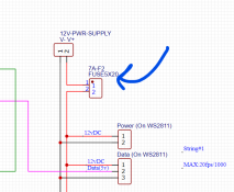
I think the only big question I have left right now is fuses. Do I need them? I had these 7A ones in my cart from before, but not sure where they would go / what they would protect. Any assistance there would be helpful!

EDIT:

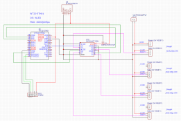
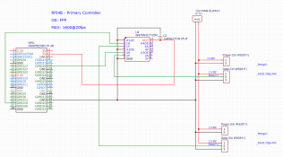
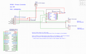
Updated schematics (Capacitor should now be right):
1703805171323.png
1703805189117.png
 
Last edited:
Do you like fires in your yard? Are you open to the risk? Do you have some other protection in place?

Fuses protect the wires. If your wires are over sized, then fuses become less critical.
I had one pixel glow nicely and melt down in setup this year. Got lucky to have smelled it before I had flames. There are some videos floating around showing actual flames as the pixel dies. It is unusual for an underloaded wire to melt. It is a forgone conclusion that an overloaded wire will melt. When it melts, the current spikes and the fuse blows.

Fuses go as close to the power source as possible.
 
Gotcha. So looking at this here, putting the 7A fuses in the box at the 12v output is correct.


For power injection runs, I am going to buy cable called "14/2 Low Voltage Landscape Lighting Wire"
The pixel lights I have are 20 gauge

I don't think it matters, but in case it does, I plan on using CAT5 (Google says 24 gauge) for data/ground runs.

1703807529918.png

One other question: If a string of 50 pixels is 15 watts (Info from Amazon listing), then that is 1.25 amps (15w=A+12v). So 500 pixels is 12A which is larger then 7A. Does this mean I cannot have that many pixels in a line, or do I have to split up the power somehow?

Thanks again!
 
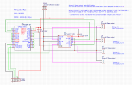
Spent a few hours preparing the schematic for PCB, and changed a few things in the process. Here are the updated ones. Please let me know if something confusing lol

1703818064816.png
1703818083274.png
 
IIWM, I would use ATM Mini Blade Fuses. I personally would limit the fuses to about 5amps as the pixel wiring is really a crap-shoot. Much of it appears to be 22awg which is rated for 5A. Since fuses protect wire, 7A fuses are a little much. Your power injection will feed as well and it should also be fused. You will probably need power injection even if you run reduced intensity. When you did your 500 pixel test, did you see color differences from start to end?

I was talking about fusing with a friend today. As we were talking, I was reminded that several of the fires people have caught did not cause the fuse to pop or much later than one would think. Still a good idea to fuse the lines as it helps with "stupid mistakes".
 
"One other question: If a string of 50 pixels is 15 watts (Info from Amazon listing), then that is 1.25 amps (15w=A+12v). So 500 pixels is 12A which is larger then 7A. Does this mean I cannot have that many pixels in a line, or do I have to split up the power somehow?"

The above is very misleading information. There have been some empirical measurements done that show that you cannot get more than 4A through the typical pixel wire. That means you never need a fuse larger than 4A on a connection from a controller to a string of pixels. This also indicates that to get to any meaningful pixel density, you will need to do Power Injection (PI).

With Power Injection, you usually have one feed line that will provide power to multiple injection points. These feed lines can therefore see more current (16AWG maxes out at 10A). This means that a good fuse for a 16AWG feed line is an 8A fuse.
Not sure where Amazon is getting its numbers. We tend to use 0.02A Per Color in a pixel = 0.06A per pixel. x 50 = 3A for a string of 50 pixels. 3A x 12v = 36W.

There are some pixels that are less bright and use less current and it is possible that there are newer pixel designs that use less power per lumen. Can you send a link to the Amazon product that has the specs you mention?
 
Back
Top