Running xLights Sequence on Raspberry Pi (And maybe an ESP device?)

In the Amazon’s listings Q&A section, someone said “if you are looking for power supplies, use the wattage. Use 15 watts per string of 50 pixels”. Hence my calculations above. I was trying to find an actual spec sheet but could not (or I just missed it), so I relied on that.


When you did your 500 pixel test, did you see color differences from start to end?
For my test, I stuck the power supply around pixel 220, so it was about the middle. When it was on the end, there very much was a brightness/color difference. When I move them outside, I’ll provide power at the start, and every 200-250 pixels.

you usually have one feed line that will provide power to multiple injection points. These feed lines can therefore see more current (16AWG maxes out at 10A). This means that a good fuse for a 16AWG feed line is an 8A fuse.
So does this mean I should have a bigger fuse (say 8A) at the start of the PI line (in the control box), and another fuse (say 4A) where the PI line meets the pixels? Or is just the 8A is needed?
 
I think you are right with that last point. Even though it’s overkill with the number of ports, the TL-SG108 looks like it will work, and is powered by 5V.
(Probably Stupid) Question: The TL-SG108 says that it takes .6A. If I take the power adapter and chop the wall adapter off and just plug it into a 5v PSU, it won’t shove more then the .6A of current at it, right?
That's correct - when everything is operating properly*, devices draw only the amount of current they need. For my 5V switch, I got a 5.5x2.1mm barrel connector and crimped some terminal forks on it. So it gets 5V from the same PSU as my Raspberry Pi. That was convenience for my sake though. I could have simply run a mains outlet into the box and plugged the included wall adapter into that to power the switch. If your PSU is providing a good 5v signal, the switch will only pull the 0.6A it uses.

*Devices draw or pull the power they need, whether or not the rest of the circuit is capable of doing it safely. As mentioned by others, if your wire is not rated to transfer the power that the pixels are providing, the resistance in the wire creates heat. The heat pushes the insulation past its ignition point, and can start a fire. Short circuits can do the same thing.
 
  • Like
Reactions: GR9
So it gets 5V from the same PSU as my Raspberry Pi.
Ok, that’s kind of what I was thinking. I have a 12v supply for my lights, and was going to buy these guys to convert the 12v to 5v. That would then power the WT32-ETC01.
I was also going to run a mains into my main control box for the Pi, Ethernet switch, and PSU.
 
A general rule is that you fuse ant any point where the wire size changes, sizing the fuse to protect the smaller wire.

In reality, I rarely do that because I use 24v feed lines and cheap 5v buck converters. The bucks will die if there is an overcurrent on the output.
 
In reality, I rarely do that because I use 24v feed lines and cheap 5v buck converters. The bucks will die if there is an overcurrent on the output.
yes i do exacly this, but 12v out and 12v to 5v buck in the field - what bucks do you use?
These have been pretty reliable, for the 18 i purchased 1 was DOA
300W 20A DC-DC Buck Converter Step Down Module Constant Current LED Driver


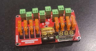
And this was my distro board i designed for xmas2023 in easyeda/jlcpcb etc...
but now that i've used it - I have a few enhancements i want to develop for next time.
2023-12-30 14_10_11-Window.png
this performed superbly

and just for laughs
i did a fps test (slowmo video on my phone) on my matrix panel (uses 2400 seed pixels over 3 ports so 800 pixels per port)
I ran a 20fps sequence - sequence was showing text 01-20 ( aligned to the sequence frame ) - slowmo caught all 20 frames
I ran a 40fps sequence - same as above but from 01-40 - slowmo caught all 40 frames

I can provide everything (sequences and slowmos) if you want to see the results yourself

@GR9 whats your easyeda username, i can share a copy of my WT32 project with you and yes i give you permission to laugh and suggest improvements.
 
Over time I have used a variety of different buck converters. I only drive 25 pixels per buck and put up to 5 bucks in a custom box,
Here is an example of one I am using in the show.

 
Ok, that’s kind of what I was thinking. I have a 12v supply for my lights, and was going to buy these guys to convert the 12v to 5v. That would then power the WT32-ETC01.
I was also going to run a mains into my main control box for the Pi, Ethernet switch, and PSU.
That's what I use to step down the voltage - I don't need the 3A provided by it, but it was a cheap and easy solution. If you wanted to consolidate things, you could run your Raspberry Pi and WT32 off of that converter. My Raspi lives in a different box anyway.
 
whats your easyeda username
Should be "greenreader9". The g may be capitalized. Some pages show it in caps, some don't lol

If you wanted to consolidate things, you could run your Raspberry Pi and WT32 off of that converter.
I read that the Raspberry Pi takes 3A itself, so I don't want to risk overloading it by placing the level shifter and ethernet thing on it as well. Since I will already be running power for the PSU, might as well just use a 3-port extension cable instead of the 1-port one I will need anyways.
 
yes i do exacly this, but 12v out and 12v to 5v buck in the field - what bucks do you use?
These have been pretty reliable, for the 18 i purchased 1 was DOA
300W 20A DC-DC Buck Converter Step Down Module Constant Current LED Driver
I use these exact ones throughout my entire display. 24V 5A feeds everywhere down to 5V 20A.
No major issues with them at all. I did build a crowbar circuit for them to kill power should the output voltage rise (failure) to protect what's on the lower voltage side.
 
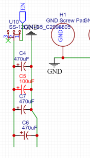
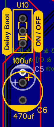
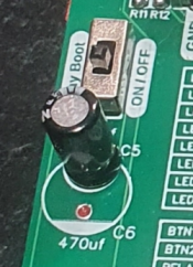
@aeiche - Thanks for sharing that! I do have a question, what is this for, and is it necessary? You have it labeled "Delay Boot", which reminds me of something I saw that mentioned the WT32 does not work right away (Or maybe it was talking about something else, I don't remember, and I cannot find that tab again). Does that sound familiar to you at all?

1704057252059.png1704057271696.png1704057296423.png

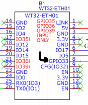
I also expanded my ET32 schematic to include data output to pixels for all the following pins:
IO0 (Pin 24)
IO2 (P15)
IO4 (P16)
IO5 (P7)
IO14 (P19)
IO15 (P20)
IO17 (P6)
GPIO33 (P8) (NOT IO33)

---

Last question for this post, I was thinking about using these guys with CAT5 cable to move the data and ground lines from the controller to the pixels. I don't think the wire gauge matters too much for those (Since it is only a 5v data line), but I wanted to double-check with you all first. The only reference to the gauge on those wires was in the Q&A section:
  • What AWG inside?
    • Thin wires, maximum 3 amps per wire, keep warm if more

Thanks for all your help!
 
Last edited:
Sorry, it is GPIO33, not IO33 (Why is this the only one using "GP"?). That must make a difference, as it does not appear to be input only1704058092867.png
 
Huh, I must have missed that.

Adding one more question for @aeiche then, what are you using in 33 for? You have it going though the level shifter, and have it set as an output in your schematics. Is it actually in use for something, or just a pin you linked up on accident?

Thanks
 
I read that the Raspberry Pi takes 3A itself, so I don't want to risk overloading it by placing the level shifter and ethernet thing on it as well. Since I will already be running power for the PSU, might as well just use a 3-port extension cable instead of the 1-port one I will need anyways.
I don't think my RasPi consumes that much power. I don't have a ammeter hooked up, so I couldn't tell you for sure, but I feel confident that running Wifi it's no more that 1.5A - at least how I'm using it. (I suspect if you were driving an HDMI display off it it'd be pulling more.)

Huh, I must have missed that

Adding one more question for @aeiche then, what are you using in 33 for? You have it going though the level shifter, and have it set as an output in your schematics. Is it actually in use for something, or just a pin you linked up on accident?

Thanks
I think you've confused me with someone else. That's not my schematic :)
 
Back
Top