Brodey
New elf
To be completely honest. I've spent well over 80 hours on this part alone. I should have asked for help a long time ago, I guess that's one of those things men really struggle with. Asking for help when they are stuck.
To make matters worse, I even found a video of a man who uses the exact hardware I have, except he uses a bread board and I do not, and I don't know how to convert bread board to wiring diagram.
Here is a list of my hardware:
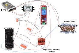
Here is my current (not working) wiring diagram:

This, I understand. Shows where wires are going, red is positive, black is negative and blue is data.
This does not work, the ESP never connects to the network when booted, despite it appearing to boot once the delay relay triggers.
I can confirm 5v is received at the ESP, 3.3v is leaving the ESP to the logic level converter, 5v is going to the high side of the logic level converter as well. This all seems fine.
Some information that might be useful:
This man:
View: https://youtu.be/GeJxolPpiE8?si=vnmUD4cpNSMxJein&t=503
(video should start at the correct time stamp)
Has the exact hardware I am using, minus the 12v to 5v converter which I need that really plays no part here. He explains why the delay relay is needed. If I only knew how to convert the bread board logic to wiring I would, this is where I am hoping someone here might be able to guide me.
He literally shows everything I have in front of me, wired perfectly. He is doing something differently to mine and I can't work out what, somewhere I am missing a wire, or a wire is going somewhere it shouldn't or to the wrong place or something.
I understand I'm missing fuses etc; disregard that. I will sort that once I have this working so when I turn on the PSU (ideally from the house), it just connects 100% of the time without me going around disconnecting a wire on each on to make it boot.
To make matters worse, I even found a video of a man who uses the exact hardware I have, except he uses a bread board and I do not, and I don't know how to convert bread board to wiring diagram.
Here is a list of my hardware:
- 3.3v to 5v Logic Level Converter Module
- NE555 DC Delay Relay (5v version)
- DC to DC 12v to 5v Step Down Converter Module (5v, 3a output)
- WT32-ETH01
- Wago Connectors
- 12v Power Supply
Here is my current (not working) wiring diagram:

This, I understand. Shows where wires are going, red is positive, black is negative and blue is data.
This does not work, the ESP never connects to the network when booted, despite it appearing to boot once the delay relay triggers.
I can confirm 5v is received at the ESP, 3.3v is leaving the ESP to the logic level converter, 5v is going to the high side of the logic level converter as well. This all seems fine.
Some information that might be useful:
- If I take out the logic level converter from the above, it will work and connect but my LEDs will just flicker or flash (it needs the logic level converter for this to stop).
- If I put back the logic level shifter and remove the delay relay, it works flawlessly, data sends, lights show properly, no issues. But, I need to disconnect the ESP and reconnect it after the PSU has booted, just a real pain, hence the need for the delay relay which will let the PSU get to 12v beforehand.
This man:
View: https://youtu.be/GeJxolPpiE8?si=vnmUD4cpNSMxJein&t=503
(video should start at the correct time stamp)
Has the exact hardware I am using, minus the 12v to 5v converter which I need that really plays no part here. He explains why the delay relay is needed. If I only knew how to convert the bread board logic to wiring I would, this is where I am hoping someone here might be able to guide me.
He literally shows everything I have in front of me, wired perfectly. He is doing something differently to mine and I can't work out what, somewhere I am missing a wire, or a wire is going somewhere it shouldn't or to the wrong place or something.
I understand I'm missing fuses etc; disregard that. I will sort that once I have this working so when I turn on the PSU (ideally from the house), it just connects 100% of the time without me going around disconnecting a wire on each on to make it boot.

