Navigation
Install the app
How to install the app on iOS
Follow along with the video below to see how to install our site as a web app on your home screen.
Note: This feature may not be available in some browsers.
More options

You are using an out of date browser. It may not display this or other websites correctly.
You should upgrade or use an alternative browser.
You should upgrade or use an alternative browser.
2023 Journey - First display for JohnnyBoy
")
tterbo_1988
New elf
- Joined
- Oct 23, 2025
- Messages
- 29
What are
What are these small boxes you are using?
Push Button Speaker Build!
Been busy the last few weeks waiting for all the parts to arrive to put together a push button speaker button. I got a lot of the help from this YouTube video
View: https://www.youtube.com/watch?v=l-fVvqQ4RgQ
it's well worth the watch and answers a lot of questions I had about the build. Lots of other questions (mainly about programming the relay (Mode P1.2 is the one you want) were answered by doc google.
I couldn't find the exact parts in the above video but managed to get close. If anyone is interested, the push button is a retro arcade button! I don't know how waterproof it is, so I bought a bunch of them and will swap them out as needed. I figure I can always put a little hood or something on the sign when I get around to it, that's future me's problem.
Parts list
DC 12V 24V 120W*2 TPA3116 D2 Dual Channel digital Power audio amplifier board
12Vto 5V DC-DC Step Down Charger Power Module Dual USB Output Buck Voltage Board 3A
DC 6-30V Support Micro USB 5V LED Display Automation Cycle Delay Timer Control Off Switch Delay Time Relay 6V 9V 12V 24V
FM Radio Receiver Module Frequency Modulation Stereo Receiving PCB Circuit Board With Silencing LCD Display 3-5V LCD Module
33mm Arcade Push Button Led Momentary illiminated Transparent Buttons with Micro Switch
View attachment 22904
Firstly I put together a test set up in the most dodgy way possible with all the electrical tape and miss-matched wiring colours. It only took me two blown fusses to figure it all out! A win in my book.
12V power is delivered by a 2pin power injection wire that will come directly off my little power distribution boxes, meaning no need for dedicated power supply in the box.
View attachment 22903
Once i figured out the amp and timer, it was trying to intergrade a FM receiver so i could have an all-in-one solution. Just give the box power and connect up some speakers. Instant party! I tried to use side cutters to remove one of the USB headers.......it did not go as planned, luckily there are two ports and I could use the other one. I ended up just soldering to the back of it, it worked much better that way. The two outside pins are + & - for those that are interested.
I have discovered that I am not the best as soldering.... I can't tin very well, and I seem to just add more solder until it sticks together.......Hopefully as I progress through this hobby my skills will improve. A better soldering iron would probably help.
Last thing that didn't really work in my favour is putting it all in this very small box. Bud Box NBF32004 - 150 x 100 x 70. It's all I had laying around and didn't want to buy another one. It fits but I had to get creative with mounting and there might be a few stray holes in the acrylic from failed mounting attempts.
But it's done! Another item ticked off the to do list! Checked it all worked with the FM Transmitter from Light-It-Up and worked a treat! Got a set of large floor stand speakers from the local Buy Nothing Page for free and ready to rock.
Very impressed with the sound level this little amplifier puts out as well!
If anyone is interested in a wiring diagram let me know!
View attachment 22907
Next job is to finish drilling the last of the holes in the electrical conduit and start pixel pushing. Hopefully can get back to that in the next few weeks!
What are these small boxes you are using?
- Thread starter
- #93
Smaller ones were Bud boxes NBF23004 – 150x100x70 that were purchased from Digi Key.What are
What are these small boxes you are using?
Though I have since upgraded to a bigger box (290x190x140) as i found the smaller one too hard to fit everything in neatly.
I got these from https://www.hansonelectronics.com.au/product/box-290x190x140/
Have a read through https://auschristmaslighting.com/th...er-as-presented-at-the-perth-2023-mini.15467/ as it provides more info and details what changes i made for better audio quality.
tterbo_1988
New elf
- Joined
- Oct 23, 2025
- Messages
- 29
Where are you powering your injection Boxes from is it a separate PSU just for them or are you using power from other control boxes?Box 3 Ground - 2 receivers
- F48 input 9 & 10
- Channel 33-40
- 2x600w PS
View attachment 22817
View attachment 22818
Box 4 Ground - 3 receivers
- F48 input 1-3
- Channel 1-12
- 3x600PS
View attachment 22819
Building the Boxes
I've managed to put together the F48 box and one of the 2 receiver boxes. I didn't take a photo of the F48 as yet, but i'll upload one when i get the chance.
I may upgrade the timers to a wifi enabled version, but these will still do the job.
Fans/Covers - da.share
Receivers - Hanson
PS - Lightitup
Box - Digi key Bud 23026
Mounting plates - Extreme Lighting
View attachment 22820
Injection Boxes
As i want to limit the length of the PI extension cables as much as possible, i've constructed a bunch of power injection boxes that will enable a large 6mm2 cable from the PS to the PI box that i can locate right near the props. More work yes, but hopefully this simplifies connections a little, and has less cable length overall, time will tell. At this stage i haven't figured out what power connections i will be using. I have a few options and would appreciate any feedback for use on 12v
- Powercon - these seem to be limited to 20A, but i believe this is at 240v? I do like the simplicity of the connection though
- Solar power connectors - i think this is the option i'll use as they are designed for 12v. Costs do add up for these.
- EC5 connectors with heat shrink. I have a bunch of these already from my RC days, not water proof, but i could use heat shrink to make them quite water tight. Its the free option and i quite like that price! Plus they have some crazy current carrying ability.
View attachment 22821
I've got lots of projects in the works for mounting etc and will update the post regularly when i get the change.
Comments and feedback always welcome!
- Thread starter
- #95
They are from the same Power supply that the receivers/controllers are supplying data.Where are you powering your injection Boxes from is it a separate PSU just for them or are you using power from other control boxes?
As i am typically powering 600+ pixels per port, they need power injection. As all my power injection is from the same power supply, i dont have to worry about breaking positive's etc. It's one way of doing it, not the best, not the worst.
tterbo_1988
New elf
- Joined
- Oct 23, 2025
- Messages
- 29
I am working through this now for next year.Mega Tree!
I dug a hole!
In my defence it was a very deep hole and I’m really proud of said hole. I work in construction and found this in the rubbish pile and then have been hanging onto this big bit of conduit since Jan 2023. I just knew it would be perfect for a Mega tree footing back when I though my display would cost $5k! It was a simpler time, with more money in the bank and no idea of the lack of free time I would have due to the blinky blink. It was in a slightly used condition when I got it, however a quick trim with a circular saw cut it down to 1100mm and was ready to sit in my garden bed……for 9months. Thanks understanding wife!
When the time came to dig the hole, I looked at my shovels, spades and digging things and realised I was not prepared for that level of manual effort. Enter the Auger drill bit! What a beast and made the job so much easier. It still took a lot of work with a tiny spade to dig out all of the sand from the hole one it was loosen, but I’ll take loosened dirt over compacted ground any day of the week! Pro tip, put a large bit of wood/table top near where you want to drill/dig your hole. It distributes the weight over the hole evenly and will prevent cave ins. Then again maybe you live somewhere that doesn’t have sand for garden, or even a garden! Fancy!
With the hole dug, I backfilled the outside and watered it in every shovel full of sand to make sure it was all compacted and sturdy. Filled the bottom of the hole with half a bag of aggregate to allow for draining through the pole conduit, and sized up a conduit liner to match the pole that I bought. 4 bags of 20kg readymix concrete and jobs done!
View attachment 24060
Mega Tree Design
Before my transport shenanigans below, deciding on a mega tree design was a choice between two different options with pros and cons.
There are many other variations of the above two designs but those links give you a good overview of both. For me it came down to not wanting to have a winch under load for the whole Christmas season. I’m sure its fine, but I don’t like things under tension. So for that reason it was ASAP all the way. (I went with the ASAP Sr Single Stage for those readying the guides linked above)
- ASAP (A strap and pole) style
- Winch midway up the pole that lifts via the winches from the bottom
- Magic Christmas - Home
- Sasquatch Style
- Winch midway up the pole that winches from the top over a pully.
- Sasquatch™ MegaTree™ Kit – Mattos Designs LLC
For those in the USA, getting the parts listed in the ASAP guides is trivial and imperial measurements mean something to you. I look at it and can read it but nothing sinks into the grey matter. As it turns out Aussie metric stuff is just as weird and our sizing lines up to the tenth of a millimetre…..weird.
Checking the Rigid Metal Conduit (RMC) sizing vs our Aussie equivalent Medium Galv Pipe does the job nicely, with only slight variances in the wall thickness.
- 1” RMC = MGP 20NB – OD 26.9mm, ID 21.7mm, Wall 2.6mm (RMC is 3.2mm)
- 1.5” RMC = MGP 40NB – OD 48.3mm, ID 41.9mm, Wall 3.2mm (RMC Wall 1.65mm)
- 2” RMC = MGP 50NB – OD 60.3mm, ID 53.3mm, Wall 3.5mm (RMC Wall 3.7mm)
The ASAP comes with a few USA things that aren’t that easy to locate.
The Winch Assembly.
- Gate Hinge for 2” Pipe
- Hinge,Pipe Gate 2" : Amazon.com.au: Home Improvement
- Don’t trust what the listing says, its only the 1 gate hinge rather than the 5 pieces I thought it came with. I bought this one as a backup in case my next idea didn’t work (it totally worked!).
- Don’t buy this
- Flange Plate to connect to topper plate
- Flange Round 40nb Galvanised (F40R) : Rural Fencing & Irrigation Supplies Perth (ruralfencingsupplies.com.au)
- I have since found out that you can get pipe that has threaded ends, and this would make an excellent/cheaper option to the way I went. I had already bought the non-threaded steel before finding the threaded version so was a bit redundant.
- Exhaust Clamps
- Spareco Exhaust Clamp - C11, 60mm (2-3 / 8 inch) | Supercheap Auto
- You want at least the C11 60mm size for the pipe. Fits nicely and quite cheap and nice to find in a local shop.
- Imperial Bolts
- While imperial bolts are easily found at the big green shed, I just had to go metric. M8 does the job for everything.
- Metal Spacers
- Can’t really give much guidance on this one, I found some in the garage. No idea what they were from but does the job. I don’t think metal spacers would be too hard to get. If they are, just go crazy on stacking bolts/washers up on top of each other. Same same.
The winch plate is really dependent on the winch you get, and that will determine the spacing. I used this cheap as chips winch from Kogan for $29. https://www.kogan.com/au/buy/costco...le-boat-trailer-4wd-winch-hand_winch_1500lbs/ Should do the job nicely.
For the plate itself I repurposed an old aluminium sign. Hopefully the messaging on the sign isn’t ominous! Thickness is 1mm, so I doubled it up to 2mm and from the test I have done should be fine. For a little more strength, using 3-5mm steel would also work well. I cut it down to size on the miter saw and rounded the edges with an angle grinder. 8mm holes were drilled on the drill press then a quick coat of black spray paint to finish it off.
View attachment 24061
What I used
For the hardware I went the stainless steel everything, really not needed but I am an overkill type of person. I found Fastner Factory really good and the prices where good considering the location options. I went with STAINLESS STEEL HEX SET BOLT A2 (304) M8x130 - 25pc (thefastenerfactory.com.au) The Full theaded type is important and recommend you get that type. I basically just cut down some bolts with an angle grinder to get the smaller sizes rather than buying smaller bolts. I only needed a few and not cost effective to buy multiple sizes.
- 4 x 60mm pipe clamps
- 4 x 130mm M8 bolts
- 4 x 40mm M8 bolts
- 1 x 20mm M8 bolt. Middle bolt. As this one should be as flat as possible, I took to it with the angle grinder to flatten it out. I still may flatten it out a little more if I get time.
- M8 washers and nuts
- 4 x steel spacers (found in my garage) or a bunch of nuts to required height.
- 4 x plastic/pvc spaces. 15mm pvc would do the job, but again I had some plastic spacers in my garage so used those instead. Doesn’t have to be anything fancy, just something to enable the steel push pole to slide past in a snugish fit.
And just like that, its was done.
View attachment 24062
Car of Steel
I was all set to get the steel delivered when I looked at the delivery price $140!!!! I live less than 10mins from Midalia Steel so quick measure of the car and figured I could Magiver it in and save on the delivery fee. Asked the guys to cut it down the 6.5m lengths to 3.6 and 2.9m sections. Fits like a glove!
Time to put it all together Md stand in the hole to give a it a test fit. Putting the poles in a few at a time wasn’t too bad, but when it came to remove it all together. WOW it is heavy, even without the metal topper, mega star and other crap hanging off it. Will definitely be a two/three person job!
The plan is to do a detailed separate Mega Tree write up when i get some time with more detailed photos and plans. One of the biggest hurdles i found with making the ASAP design was just trying to interpret the online plans. Hopefully I can have a crack at it and help the community a little.
View attachment 24063
The Topper and Topper Connections
So while the OG ASAP guide uses those gate clamps I wanted an easier way. Enter pole handrail fittings. They are designed for 40NB sizing exactly so work perfectly. Ezayrail 140 Gate Hinge vs the original design. Waaaaay easier and locally available for much much cheaper. $13.42 AUD plus postage! Ezyrail 140 - Gate Hinge Male Part - Safety Xpress
This led me to the four fixing base flange, at $34.21 its quite a bit more than the flange plate I linked before but as I didn’t have threaded pipe this was the option I found. I originally was going to get something custom fabricated from a metal shop, but why bother when something like this exists for reasonable money. Ezyrail 234 - Four Fixings Point Square Base Flange - Safety Xpress
View attachment 24064
The Steel topper is from Piptree Designs. Awesome quality and locally made! Check them out at Mega Tree Toppers | Piptree Designs (square.site) I have unfortunately found out that they are out of stock for the 2023 Christmas season, but check back in 2024, the quality is really something awesome for reasonable prices.
So a quick sand down to get rid of some minor service rust and 3 coats of black to make it look all flash. For the topper, I couldn’t go past the 270pix star! Add in some 3D printed mounts to connect the steel topper to the mega star and I was set. Cable ties are doubled up and ive given it the ‘its got going anywhere’ shake. I really am impressed by the strength of the conduits and fittings, way stronger than it looks. I hope! Some extra cable ties will be put over the 3D printed mounts when it’s ready to go up. As I’m still moving it around I wanted the ability to disconnect the star from topper easily.
A AliExpress purchase rounded out the M6 stainless steel hooks for the mega tree strips. 32x150 strips of lighting goodness! The two eyelets at the back will be for the guy wires.
View attachment 24065
I think I am 95% ready for Christmas, with setup planned for mid Nov. Hopefully I find some time from now until then for the rest of this write up.
Task done but not written up
To do tasks
- House mounts
- Showstopper mounts
- Getting FFP working and my temp setup
- House networking and permanent FPP/Beaglebone setup
- Sequencing
Until next time, happy blinky
- Push button mount pole
- Push button plate
- Facebook page setup
- Setting up a charity donate page/QR coded
- Put everything up!
you said you have the lengths cut to 3.6 and 2.9. from what I can see I will only need one length of 50nb, 40nb, 20nb all cut to 9'10'' =2.9 mt.
are the extra because you had to buy the complete lengths? or making a second lol.
did you use the extra 20nb for the bottom?
this thread has helped me a lot in my journey so far and planning ahead.
- Thread starter
- #97
Lengths all depend on hole depth and how high you want the mega tree to be.I am working through this now for next year.
you said you have the lengths cut to 3.6 and 2.9. from what I can see I will only need one length of 50nb, 40nb, 20nb all cut to 9'10'' =2.9 mt.
are the extra because you had to buy the complete lengths? or making a second lol.
did you use the extra 20nb for the bottom?
this thread has helped me a lot in my journey so far and planning ahead.
The steel only came in 6.5m lengths, so the cuts were based on what i needed (and that would fit inside my car). Ive still got the left over bits from the 50nb and 40nb down the side of my house....my wife is thrilled! I've thought about a second mega tree, no idea where it would go though!
I used all of the 20nb 6.5m length. Half for the push stick that pushes up the 40nb piece up via the winch. The second piece i got bent up into a half circle to fix the pixels to at the bottom. Most use a small trampoline base, but i had the steel sitting there, so why not.
tterbo_1988
New elf
- Joined
- Oct 23, 2025
- Messages
- 29
yeah my steel supplier will sell it by the meter so that is a bonus. I would be looking at around a 4 mt tall, and a base with a diameter of roughly 2mt for the bottom. Unsure weather i go 100 or 150 pixels per strand. I am renting atm so will use the portable hole with four threaded bars. I will get a base plate welded to the bottom of the 60mm NB pipe to mount it to the portable hole. or maybe use a piece of conduit in the block. I think i will run alternate nodes so starts and end at the bottom for easy power injection.Lengths all depend on hole depth and how high you want the mega tree to be.
The steel only came in 6.5m lengths, so the cuts were based on what i needed (and that would fit inside my car). Ive still got the left over bits from the 50nb and 40nb down the side of my house....my wife is thrilled! I've thought about a second mega tree, no idea where it would go though!
I used all of the 20nb 6.5m length. Half for the push stick that pushes up the 40nb piece up via the winch. The second piece i got bent up into a half circle to fix the pixels to at the bottom. Most use a small trampoline base, but i had the steel sitting there, so why not.
silver_ice
New elf
- Joined
- Jan 6, 2023
- Messages
- 34
@tterbo_1988 Definitely do 4 metres, 150pix per strand at 1in/25mm, 2 metre base diameter - I run 2 of these exactly, 30 x 150 pixels they look unreal and you can run video on them, I'll get some pics for you in a bit. FWIW I poured a couple of 500x500x500 concrete cubes I use as my portable holes
tterbo_1988
New elf
- Joined
- Oct 23, 2025
- Messages
- 29
Thanks that’s what I am looking at doing does anyone know where to source a topper the pup tree website doesn’t appear to have them anymore@tterbo_1988 Definitely do 4 metres, 150pix per strand at 1in/25mm, 2 metre base diameter - I run 2 of these exactly, 30 x 150 pixels they look unreal and you can run video on them, I'll get some pics for you in a bit. FWIW I poured a couple of 500x500x500 concrete cubes I use as my portable holes

Mega Tree Topper - Ink Creations | Digital Printing | Christmas Light Props
No Mega Tree is complete without a show-stopping Mega Tree Topper. Made Locally from Precision cut 5mm Steel. Available in 4 sizes all 360°.
silver_ice
New elf
- Joined
- Jan 6, 2023
- Messages
- 34
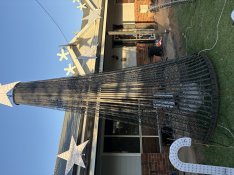
Ok so here is my DXF for the topper, lasercorp or ferracut or any laser place can do it, 6mm mild steel, works good (https://auschristmaslighting.com/threads/welding-mega-tree-topper.16942/#post-143584)Thanks that’s what I am looking at doing does anyone know where to source a topper the pup tree website doesn’t appear to have them anymore
Here is my tree, 4mtr + star, in concrete base, I have 2 of these and love them
Attachments
tterbo_1988
New elf
- Joined
- Oct 23, 2025
- Messages
- 29
Thanks heaps for sharing the DFX Files!! I was about to start drawing my own but you have saved me a lot of timeOk so here is my DXF for the topper, lasercorp or ferracut or any laser place can do it, 6mm mild steel, works good (https://auschristmaslighting.com/threads/welding-mega-tree-topper.16942/#post-143584)
Here is my tree, 4mtr + star, in concrete base, I have 2 of these and love them