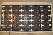
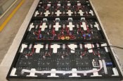
P10 Panel - What is it and how to connect it?

David_AVD said:
I think Phil mentioned somewhere that the P10 panels from Ray (using RGB 5050 LEDs) draw a little under 1A (@ 5V) each on full white.

This is true when running them from the BBB + Octoscroller + FPP combination. Mine drew 0.9A max each when I tested them under those conditions.

But.... if you're using a different controller each panel can draw up to 2.9A (@ 5V) on full white.


Nice information David, that was a very improptu measurement and surprised me it was quite that low.


As 1/8 scan panels and assuming the standardised 20mA per colour you have 64 leds turned on at any one time for 64 leds x 60mA and 3.84A per panel


Now assume 15mA you get 2.88A which is pretty damn close to 2.9A, this assumes zero switching time between each scan....


I can only assume that octroscoller code has a much shorted on time versus the off time for each scan.


It will make it interesting if the octoscroller code gets tweaked and all of a sudden 1000's of panels are under powered undercabled :)


cheers
 
The LED current is set by a resistor on each CC drive chip. I don't recall its number off the top of my head but did find a data sheet (in Chinese) for it.

I'd have to check my code, but I think the OE is only disabled for a very short time (< 20 us at a guess) while the ABC select lines and latch are being changed after the data is clocked in for each scan row (every 1ms). That's why my setup was so much brighter and current hungry. I implemented dimming on a whole panel basic by using PWM on the OE line.
 
I'm almost doing building my panel except that it will need a housing to waterproof it. I used a solid sheet of plexiglass for mounting the panels. Mine is 4x5 panels which will give 128x80 pixels. It's 1280mm x 800mm. The link below the photo has a DXF drawing I used to cut the plastic on my CNC. My machine only cuts 4'x4' material so there are 4 holes used for alignment since I had to cut in 2 phases.
P10PanelsMounted.jpg


Backing panel drawing:
https://www.mediafire.com/folder/n55fqava1aq33/CNC
 
to the comment about can a FPP raspberry Pi and a FPP BBB be connected together? Yes


FPP is the software, ur runs on either a Raspberry Pi or a Beagle Bone Black. rPi has much better video output. I run my master FPP as a rPi. BBB has 40-50 output pins (vs rPi's 8). BBB has way more processing power BBB was picked to drive the parallel needs of a P10 panel displays.


Can they both work together? yes. How many slave FPP's? I think it is 16 million.


So , theoretically you can have 1 master and 16 million salves. Since each FPP (either rPi or BBB) can drive 80K channels, you could have over 1 trillion channels.


Every slave will be kept synced to the master within +/- 1 frame.


I had 1 master and three slaves last year , each had a projector. All were in perfect sync.


Your slaves can be located in any part of the world (Just need to be able to ping the ip address).
Imagine creating a show in Australia, 1000 people around the world have loaded up your fseq files and set their FPP's into slave mode. You run your sequence, the entire world syncs and runs.


We should setup a world FPP day


So , go ahead and mix and match rPi and BBB's, just remember one master to rule them all...
(For the NZ folks)
 
smeighan said:
We should setup a world FPP day

Sean,

We should appeal to the United Nations to establish an "International Day of the Falcon".

When the Falcon/xLights team finishes their work and thousands have been embodied with the Pi/FPP magic, we can all take our Pi/FPP/Projectors to our local City Hall buildings and at precisely 12:01AM on May 18, 2017 , the day after "World Telecommunication and Information Society Day", we can all project a visual butterfly in Falcon speak on our City Halls exterior, calling for the freedom of geeks everywhere.

Just a thought--I'll move on...
 
For those of us not using projectors we had better configure out P10 panels so that they can be mounted on the roof of our cars or alternately as wearable sandwich board "devices".

Charles Belcher said:
smeighan said:
We should setup a world FPP day

Sean,

We should appeal to the United Nations to establish an "International Day of the Falcon".

When the Falcon/xLights team finishes their work and thousands have been embodied with the Pi/FPP magic, we can all take our Pi/FPP/Projectors to our local City Hall buildings and at precisely 12:01AM on May 18, 2017 , the day after "World Telecommunication and Information Society Day", we can all project a visual butterfly in Falcon speak on our City Halls exterior, calling for the freedom of geeks everywhere.

Just a thought--I'll move on...
 
Gilrock said:
I ended up using #10 screws as a terminal post and it worked out much better than the terminal blocks I was initially trying to wire up.

Not sure exactly what you mean there. Do you have a closeup of that bit?
 
smeighan said:
Your slaves can be located in any part of the world (Just need to be able to ping the ip address).
Imagine creating a show in Australia, 1000 people around the world have loaded up your fseq files and set their FPP's into slave mode. You run your sequence, the entire world syncs and runs.


We should setup a world FPP day


So , go ahead and mix and match rPi and BBB's, just remember one master to rule them all...
(For the NZ folks)

Now your just scaring me Sean, you guys are amazing
 
David_AVD said:
Gilrock said:
I ended up using #10 screws as a terminal post and it worked out much better than the terminal blocks I was initially trying to wire up.

Not sure exactly what you mean there. Do you have a closeup of that bit?

I can take a closer photo but not for several hours. I originally bought terminal blocks but it's a pain to try to bridge all the circuits on the terminal block together. So I got the idea to just drill a couple holes and put 1" #10 screws in there poking outwards. One nut to secure the screw to the Plexiglas. Then I crimped on ring lugs to fit on the screws. I put 2 lugs and then a nut...2 more lugs and another nut. I split each side into it's own 2 screws mainly because the top wire just barely made it to that point but then I realized it would also divide up any current so I didn't have to worry about the gauge of the wire coming from the power supplies to the screws. I used 14 gauge for that and it's doubled up.

It ends up taking up a lot less space than terminal blocks and I thought it ended up looking cleaner.
 
Ahhh... the word "screws" threw me there. I was imagining a self tapping screw, not a machine thread bolt with nuts.

It sounds like you have this covered with the first nut, but care should be taken so that any loosening of the bolt in the plastic doesn't release tension on the terminal stack.
 
Gil, did you fuse each P10? With the capability of one power supply powering up many panels, it just seems like for safety and troubleshooting that each P10 should have it's own fuse?? How about everybody else? Should each P10 be fused? --Greg--
Gilrock said:
Ok here's the closeup I promised of the power supply wiring:
P10_wiring_closeup.jpg
 
I don't have any fuses. I don't think I've seen them on the other panels I've seen posted but that doesn't mean it's not a good idea. I thought about it but didn't take the time to do it.
 
Gilrock that CNC perspex mounting looks awesome.


As for fusing, I'd be adding them to the PSU outputs at a minimum.


I also fused mine per row - rather than per column - as apparently the panels will attempt to pull power from their neighbors if their own supply is lost. I figured it'd be better to blow the fuse for the entire row then.


My setup so far is below. This is currently in a 42x19mm pine frame as I was originally going to mount the PSU externally and I wanted a light weight unit as the matrix is not staying outside each night. However as it turned out the BBB+Octo+ribbon cables on top just didn't have enough clearance. Then as it got heavier it was behind more awkward to handle. So rebuilding it with a 89mm deep box now.
 

Attachments

  • p10-complete-v1_1.jpg
    p10-complete-v1_1.jpg
    491.1 KB · Views: 147
  • p10-complete-v1_2.jpg
    p10-complete-v1_2.jpg
    447.5 KB · Views: 128
This thread is very old. An answer might not be needed anymore.
Back
Top