Brodey
New elf
Hey,
New to the hobby, I've always just used dumb LEDs, but the guy up the road whom I have unofficially always competed with has now gone this route, so now I need too in order to be better. (yeah, I'm that kind of guy). So, I'm starting in January 2024 to have everything ready for Christmas.
Wiring is my biggest issue; I have most things or will buy most things. I have decided to go down the route of 12v WS2811 LED Strings with my connector of choice being Ray Wu connectors, and WT32-ETH01 with WLED flashed and a Raspberry Pi 4 running FPP.
The ESP32 device (WT32-ETH01) is 5v for reference.
I plan on having ~4,500 pixels (nodes) by Christmas; research on the WT32-ETH01 says for perfect performance, I can run 512 LEDs per pin for a total of 2,048 LEDs per WT32-ETH01 controller, so I'll run 3 of these. Reference: https://kno.wled.ge/features/multi-strip/#esp32
I have a couple of options for power supplies with what I have available to me already, but happy to buy something else if it'll make my life easier. I had old ETH mining rigs I had a bunch of power supplies for, some old desktop ones, and some server PSUs.
Server PSU (DPS-1200FBA) 100a: With a 12x 6 Pin Power Supply Breakout Board Module, which is 3x 12v pins and 3x Negative pins per connector.
1500W Desktop PSUs from Silverstone (SST-ST1500-GS) 120a: I can convert 6 pin adapter cables to 3x 12v positive and negative.
AC/DC Adapter (JCY-1250) 12v 5a: This is just a cheap transformer that came with 1 set of LED strings I bought, probably useless.
I think my biggest issue with wiring is the 12v lights and 5v controller, and then power injection.
I managed to stumble upon this tool: https://wled-calculator.github.io/. If I say I want to run 1,000 pixels, I will need a 20a fuse. I've never used Fuses before, and if a project required one, I typically deemed it too challenging for me. But, yet, here I am still trying.
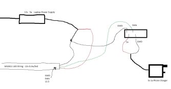
I think I need a 12v to 5v Step Down Adapter to convert my 12v negative to my v5 controller. This is my current wiring diagram.

I am using the transformer in the top left for now; the top right device is the WT32-ETH01 device, bottom left is a 5v 1a USB phone charger with the USB positive and negative wires only in use.
So, other than the ground wire going from the 12v PSU to the GWD on the controller, 5v and 12v are separated. I think this is where I need my 12v to 5v adapter to go.
In this configuration, I can get it to work if I have a 50 LED string attached and turn the controller on after I turn on the 12v power. However, the 12v transformer makes a high pitch noise, which doesn't make me feel safe. If I add another 50 Strings to the end of the other 50, I can't get it to work at all.
This is just level 1, obviously; as it gets more complex, I am just going to run 3 controller boxes with 1 controller in each, and then 5m Ray Wu cables from the box to the LEDs.
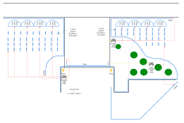
Here is a diagram of my house and my proposed setup:

So, the thick black line is my house, blue are LEDs, red is saying which controller will power which lights. With some help from Google Bard (AI), I only really need 594w of power or 5amps per string, so 1x 1000PSU would be enough, but I will run 3 to simplify wiring.
I will do a power injection every 200 pixels. This is where I'm confused. Do I run a cable from the same PSU up to the 2nd string of 100 pixels and just boost it? Because to boost, I carry a positive and a negative wire up to that point, then a positive and negative to the PSU, do I need to run a negative and another 12v to 5v adapter to run a negative from the PSU to the controller again? Doesn't make sense why I would; based on my first diagram, I already have this cable existing. Or should it not exist?
That raises the question: If I use a 12v to 5v adapter (if this is the correct thing to do), do I need fuses like the website calculator suggested I did? If so, how do I wire the fuse based on several strings and power injection?
Sorry for the long post; I only have a year to figure this out and buy all the lights, so the guy up the road doesn't show me up again.
The software side I am good at the, I'm a programmer, but I program web applications, not hardware. This is my first major hardware project; I can, however, solder, strip wires, etc, and I will be having an electrician inspect the wires etc, before running them over Christmas to ensure I'm not going to start fires or electrocute some kid riding past on the footpath (even though the kids around here might deserve it sometimes).
New to the hobby, I've always just used dumb LEDs, but the guy up the road whom I have unofficially always competed with has now gone this route, so now I need too in order to be better. (yeah, I'm that kind of guy). So, I'm starting in January 2024 to have everything ready for Christmas.
Wiring is my biggest issue; I have most things or will buy most things. I have decided to go down the route of 12v WS2811 LED Strings with my connector of choice being Ray Wu connectors, and WT32-ETH01 with WLED flashed and a Raspberry Pi 4 running FPP.
The ESP32 device (WT32-ETH01) is 5v for reference.
I plan on having ~4,500 pixels (nodes) by Christmas; research on the WT32-ETH01 says for perfect performance, I can run 512 LEDs per pin for a total of 2,048 LEDs per WT32-ETH01 controller, so I'll run 3 of these. Reference: https://kno.wled.ge/features/multi-strip/#esp32
I have a couple of options for power supplies with what I have available to me already, but happy to buy something else if it'll make my life easier. I had old ETH mining rigs I had a bunch of power supplies for, some old desktop ones, and some server PSUs.
Server PSU (DPS-1200FBA) 100a: With a 12x 6 Pin Power Supply Breakout Board Module, which is 3x 12v pins and 3x Negative pins per connector.
1500W Desktop PSUs from Silverstone (SST-ST1500-GS) 120a: I can convert 6 pin adapter cables to 3x 12v positive and negative.
AC/DC Adapter (JCY-1250) 12v 5a: This is just a cheap transformer that came with 1 set of LED strings I bought, probably useless.
I think my biggest issue with wiring is the 12v lights and 5v controller, and then power injection.
I managed to stumble upon this tool: https://wled-calculator.github.io/. If I say I want to run 1,000 pixels, I will need a 20a fuse. I've never used Fuses before, and if a project required one, I typically deemed it too challenging for me. But, yet, here I am still trying.
I think I need a 12v to 5v Step Down Adapter to convert my 12v negative to my v5 controller. This is my current wiring diagram.

I am using the transformer in the top left for now; the top right device is the WT32-ETH01 device, bottom left is a 5v 1a USB phone charger with the USB positive and negative wires only in use.
So, other than the ground wire going from the 12v PSU to the GWD on the controller, 5v and 12v are separated. I think this is where I need my 12v to 5v adapter to go.
In this configuration, I can get it to work if I have a 50 LED string attached and turn the controller on after I turn on the 12v power. However, the 12v transformer makes a high pitch noise, which doesn't make me feel safe. If I add another 50 Strings to the end of the other 50, I can't get it to work at all.
This is just level 1, obviously; as it gets more complex, I am just going to run 3 controller boxes with 1 controller in each, and then 5m Ray Wu cables from the box to the LEDs.
Here is a diagram of my house and my proposed setup:

So, the thick black line is my house, blue are LEDs, red is saying which controller will power which lights. With some help from Google Bard (AI), I only really need 594w of power or 5amps per string, so 1x 1000PSU would be enough, but I will run 3 to simplify wiring.
I will do a power injection every 200 pixels. This is where I'm confused. Do I run a cable from the same PSU up to the 2nd string of 100 pixels and just boost it? Because to boost, I carry a positive and a negative wire up to that point, then a positive and negative to the PSU, do I need to run a negative and another 12v to 5v adapter to run a negative from the PSU to the controller again? Doesn't make sense why I would; based on my first diagram, I already have this cable existing. Or should it not exist?
That raises the question: If I use a 12v to 5v adapter (if this is the correct thing to do), do I need fuses like the website calculator suggested I did? If so, how do I wire the fuse based on several strings and power injection?
Sorry for the long post; I only have a year to figure this out and buy all the lights, so the guy up the road doesn't show me up again.
The software side I am good at the, I'm a programmer, but I program web applications, not hardware. This is my first major hardware project; I can, however, solder, strip wires, etc, and I will be having an electrician inspect the wires etc, before running them over Christmas to ensure I'm not going to start fires or electrocute some kid riding past on the footpath (even though the kids around here might deserve it sometimes).


